Money clip

a clip and money technology, applied in the field of money clips, can solve the problems of lever separation, complicated and time-consuming assembly,

Active Publication Date: 2012-01-31
GERAGHTY
View PDF7 Cites 84 Cited by
  • Summary
  • Abstract
  • Description
  • Claims
  • Application Information

AI Technical Summary

Problems solved by technology

Since money clips with extendable and retractable levers include multiple slidable parts, they require precise manufacturing of the individual parts of the money clip and also require detailed and time-consuming assembly in order to produce an attractive and reliable clip.
At times, excessive force is applied by a user when withdrawing the levers which can cause the levers to separate from the body of the clip.

Method used


Image

  • Money clip
  • Money clip
  • Money clip

Examples


Embodiment Construction

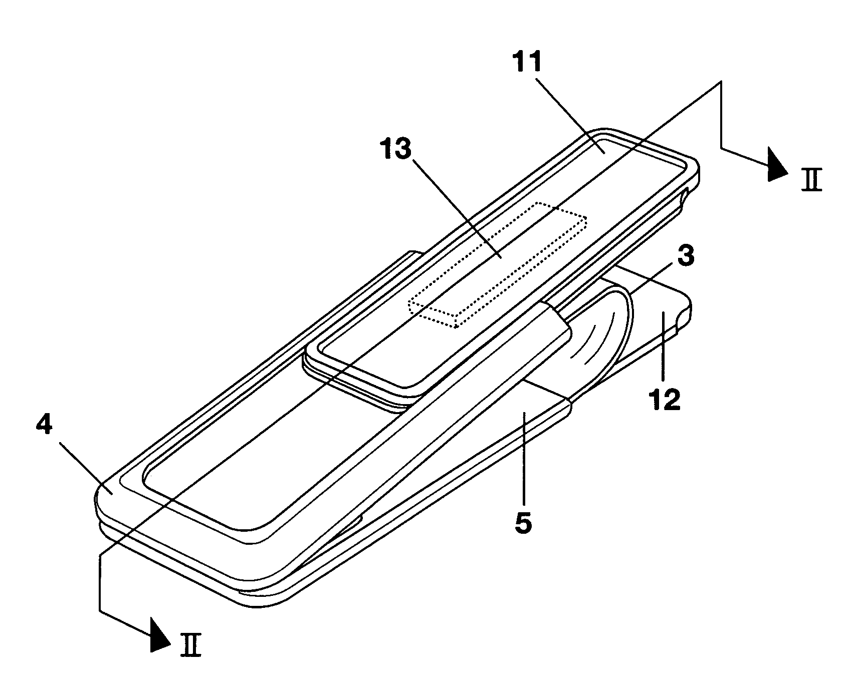
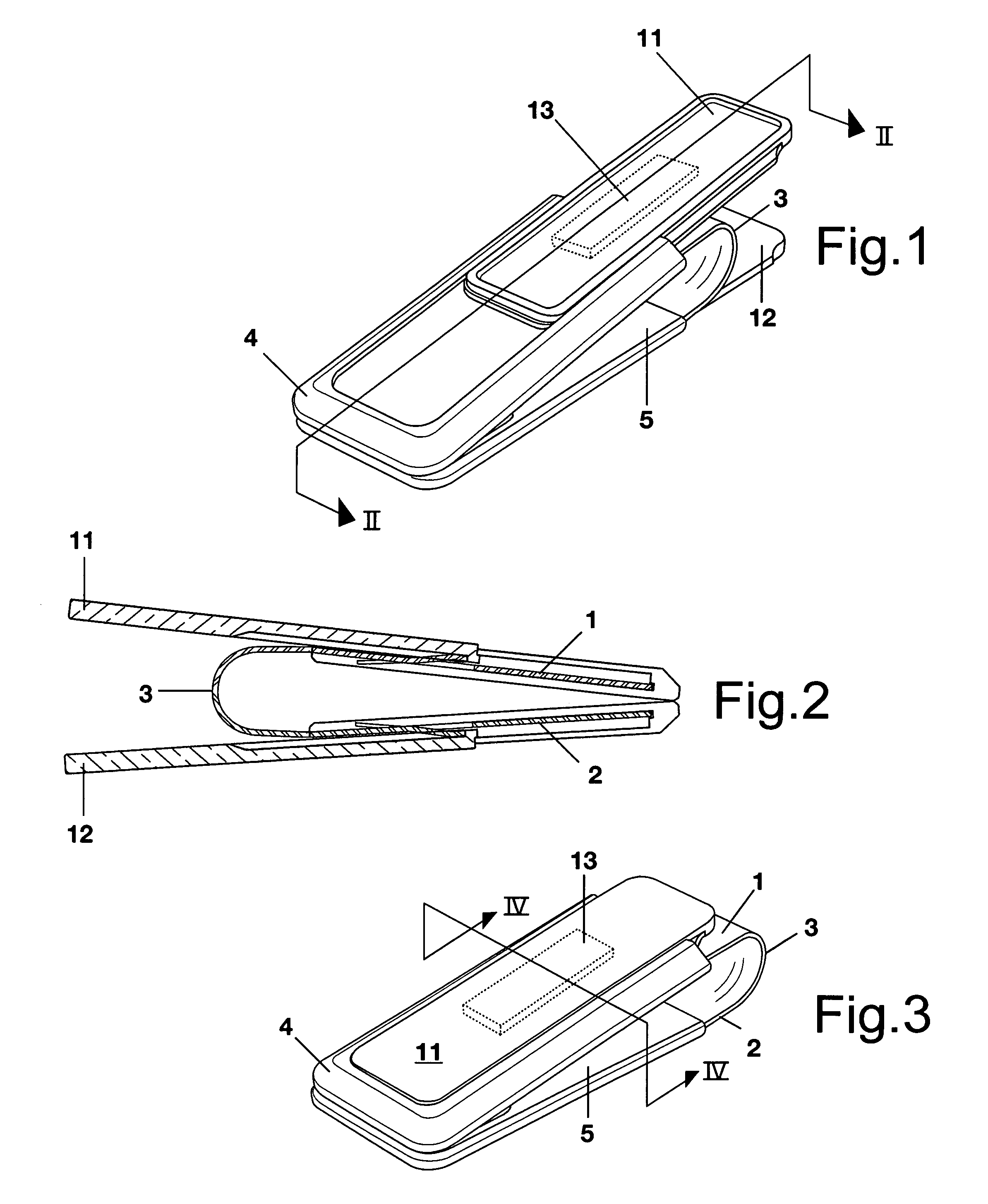
[0014]In the drawings and with particular reference to FIGS. 1-3, the money clip, according to this invention, is shown and includes a spring clip having upper and lower jaws 1 and 2 which are joined together by throat 3. As known in the art, throat 3 is spring-loaded so as to urge jaws 1 and 2 together and thereby provide the biasing force to hold the user's currency, credit cards and the like in a secure stored manner.

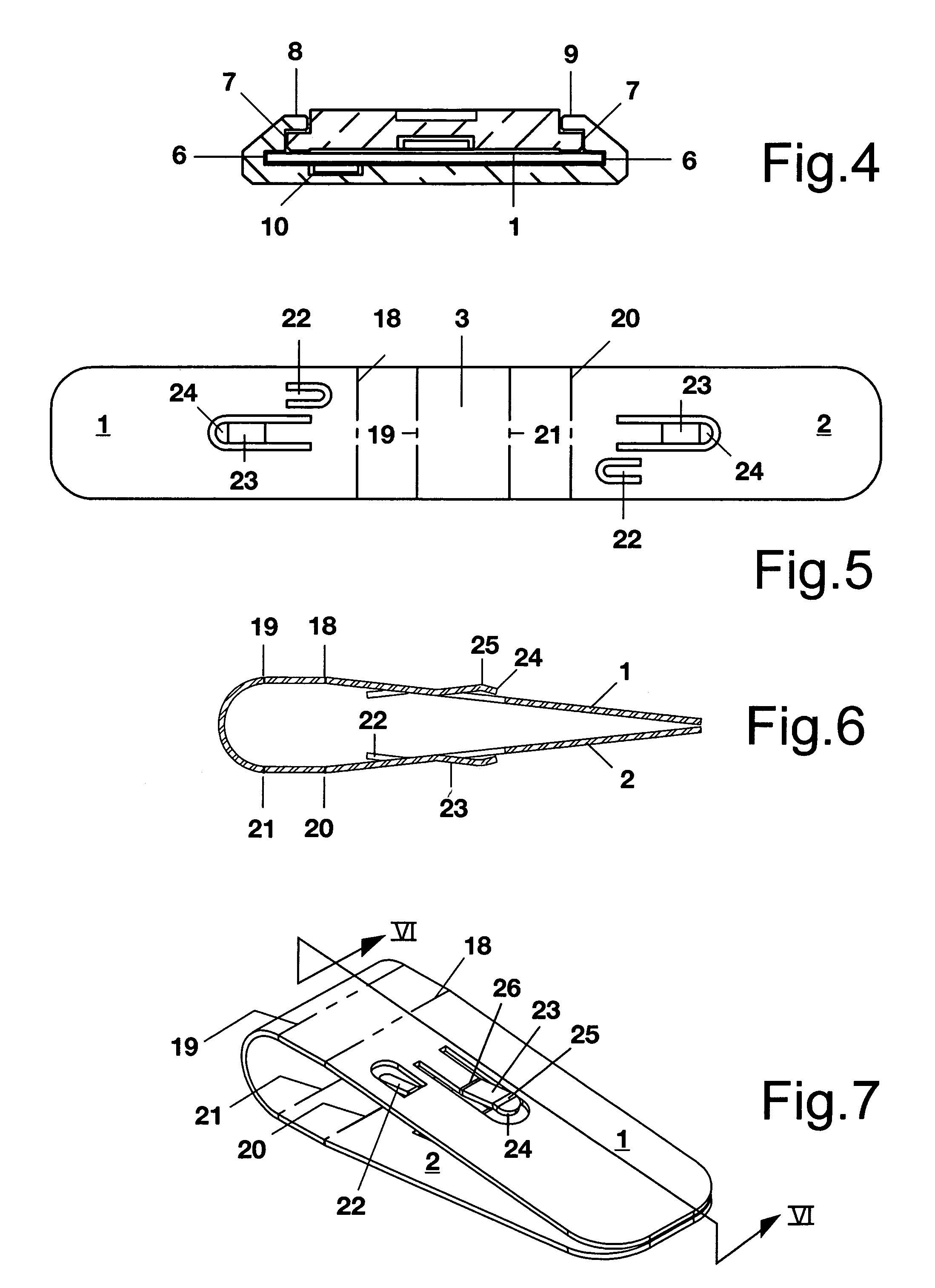
[0015]The money clip includes a pair of operating lever housings 4 and 5 which partially envelope, respectively, jaws 1 and 2. As shown in FIG. 4, each of the housings 4 and 5 has spaced elongated slots 6 and 7 with a pair of spaced elongated shoulders 8 and 9 disposed generally above and coextensive with slots 6 and 7. In addition, notch 10 is formed on the interior surface of each housing 4 and 5.

[0016]To complete the basic elements of the money clip, according to this invention, operating levers 11 and 12 are slidably receivable in housings 4 and 5, respectively. ...


PUM


Abstract

A money clip includes a pair of jaws joined together by means of a throat with a pair housings at least partially enveloping the jaws. A pair of operating levers are slidably mounted, respectively, in the housings with an elongated slot formed on the interior of each operating lever. A locking arm is attached to each jaw disposed and positioned to form an interlocking relationship between the jaw and respective operating lever.

Description

BACKGROUND OF THE INVENTION[0001]Devices to hold items such as paper currency, credit cards, drivers licenses etc. have been employed in many variations such as basic enlarged paper clips and standard binder clips which have foldable arms, all of which are well known. Advances in the art include money clips with retractable operating levers which are described in McGarity U.S. Pat. Nos. 5,946,778 and 6,988,296. Money clips with operating levers were a major advancement in that they allowed the clip to be easily and conveniently opened by squeezing the extended operating levers together and then retracting the levers to positions so that they are out of the way when not in use.[0002]Since money clips with extendable and retractable levers include multiple slidable parts, they require precise manufacturing of the individual parts of the money clip and also require detailed and time-consuming assembly in order to produce an attractive and reliable clip. At times, excessive force is app...

Claims


Application Information

Patent Timeline
Patent Type & Authority Patents(United States)
IPC IPC(8): B42F1/02
CPCA61B17/1227B42F1/06B42F1/10F16B2/22F16B2/245A61B2017/00526Y10T24/203Y10T24/44496Y10T24/4494Y10T24/44453Y10T24/4488
Inventor MCGARITY, RONALD M.
Owner GERAGHTY
Why Eureka
Try Eureka