Body frame and vehicle
a body frame and vehicle technology, applied in the direction of friction roller based transmission, steering device, cycle equipment, etc., can solve the problems of increasing the number of parts of the body frame, and achieve the effect of improving the rigidity of the first frame, improving the flexibility of the shape of the head pipe, and improving the rigidity of the second fram
- Summary
- Abstract
- Description
- Claims
- Application Information
AI Technical Summary
Benefits of technology
Problems solved by technology
Method used
Image
Examples
first embodiment
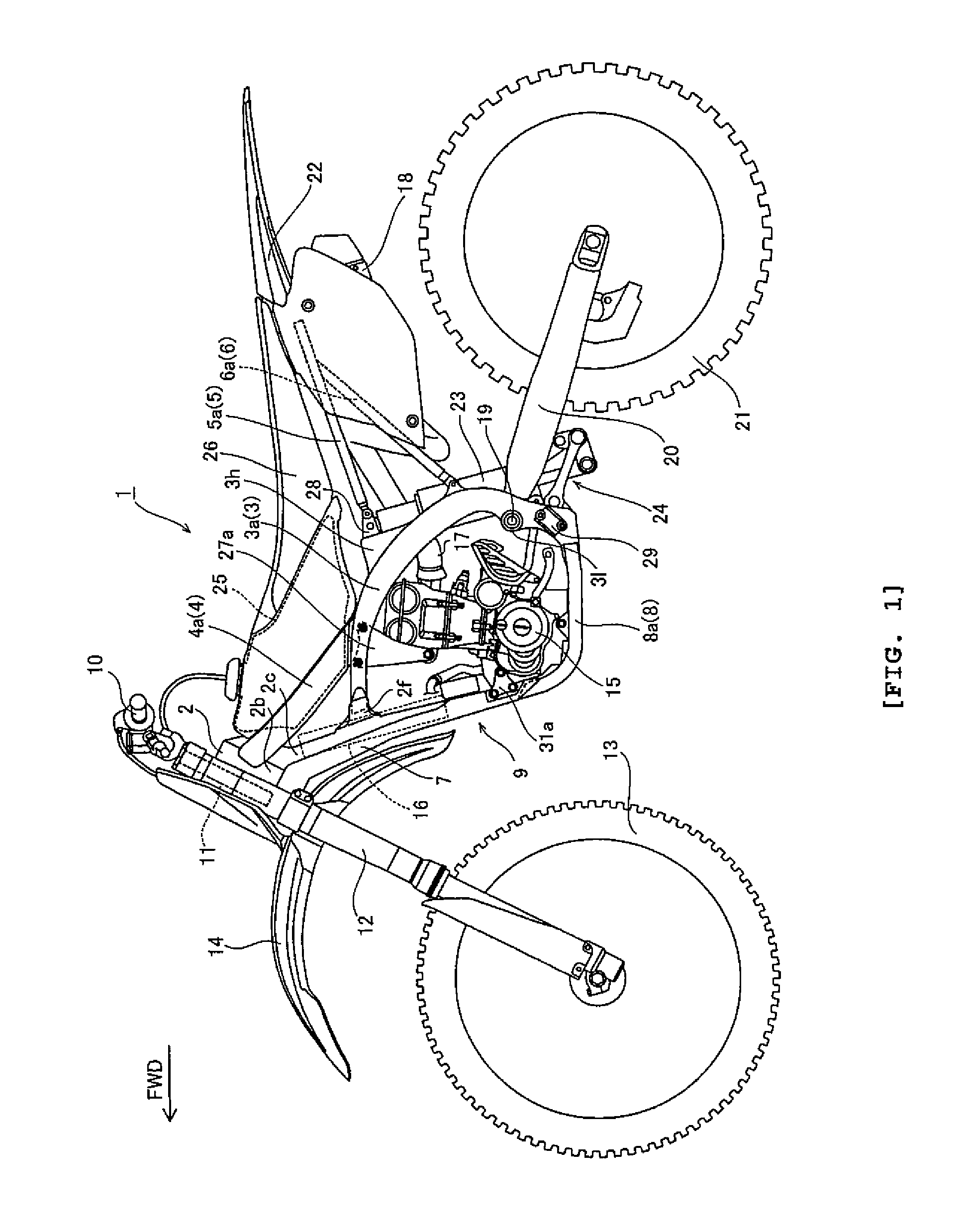
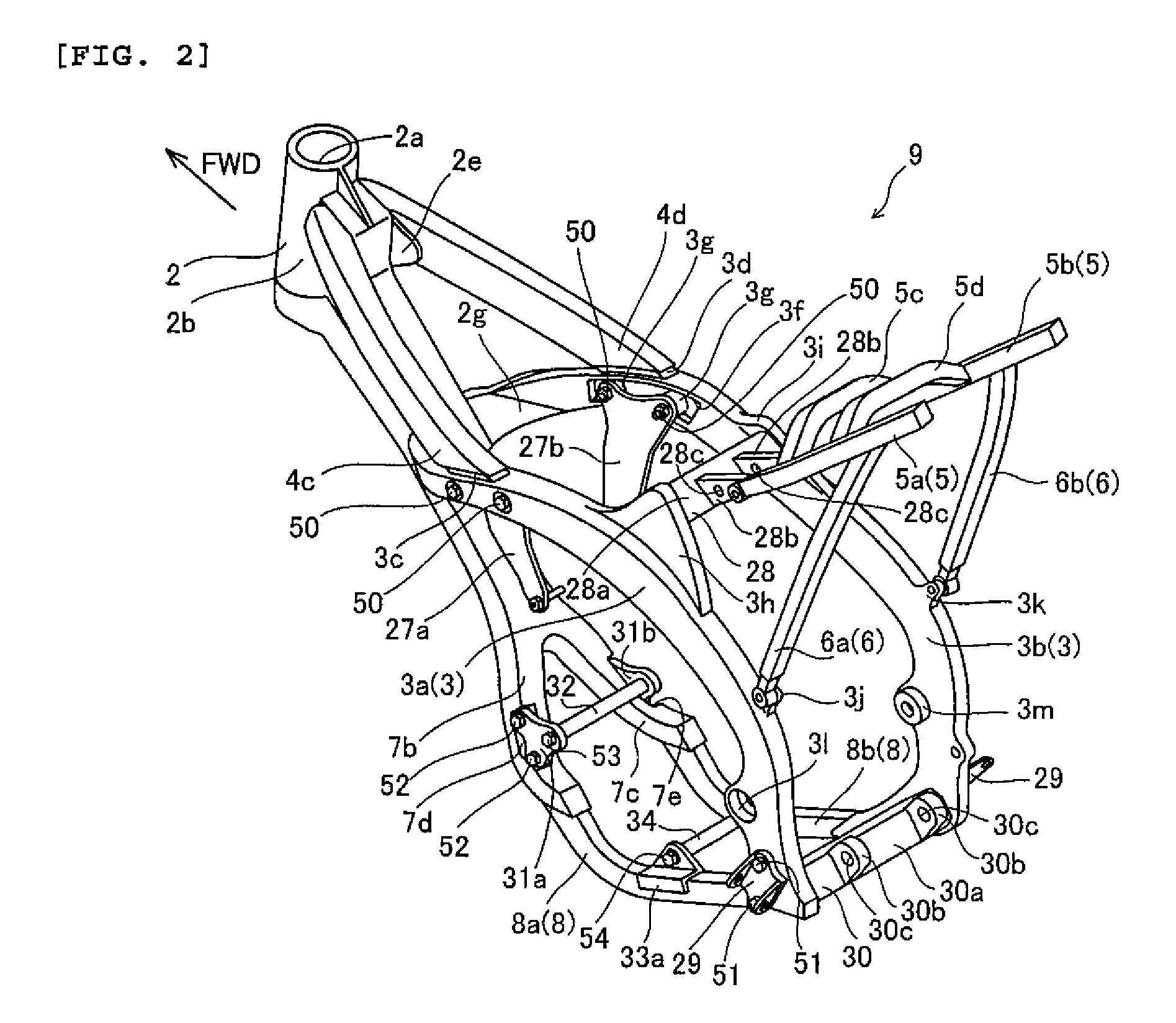
[0040]FIG. 1 is a side view of a motorcycle 1 according to a first embodiment of the present invention. FIGS. 2-11 are explanatory views of a body frame of motorcycle 1. A motorcycle is merely one example of a vehicle according to the present invention. The direction indicated by the arrow FWD in the drawings is a forward traveling direction of motorcycle 1. The structure of motorcycle 1 according to the first embodiment of the invention is now described with reference to FIGS. 1-11.
[0041]Motorcycle 1 has a main frame 3 of which a front end is directly connected to a head pipe 2. Main frame 3 extends in a downwardly rearward direction. Main frame 3 is an example of the “first frame” of the present invention.
[0042]A tank rail 4 is interposed between a rear portion of head pipe 2 and an upper portion of main frame 3. More specifically, a front end (one end) of tank rail 4 is connected to the rear portion of head pipe 2, and a rear end (other end) of tank rail 4 is connected to the upp...
second embodiment
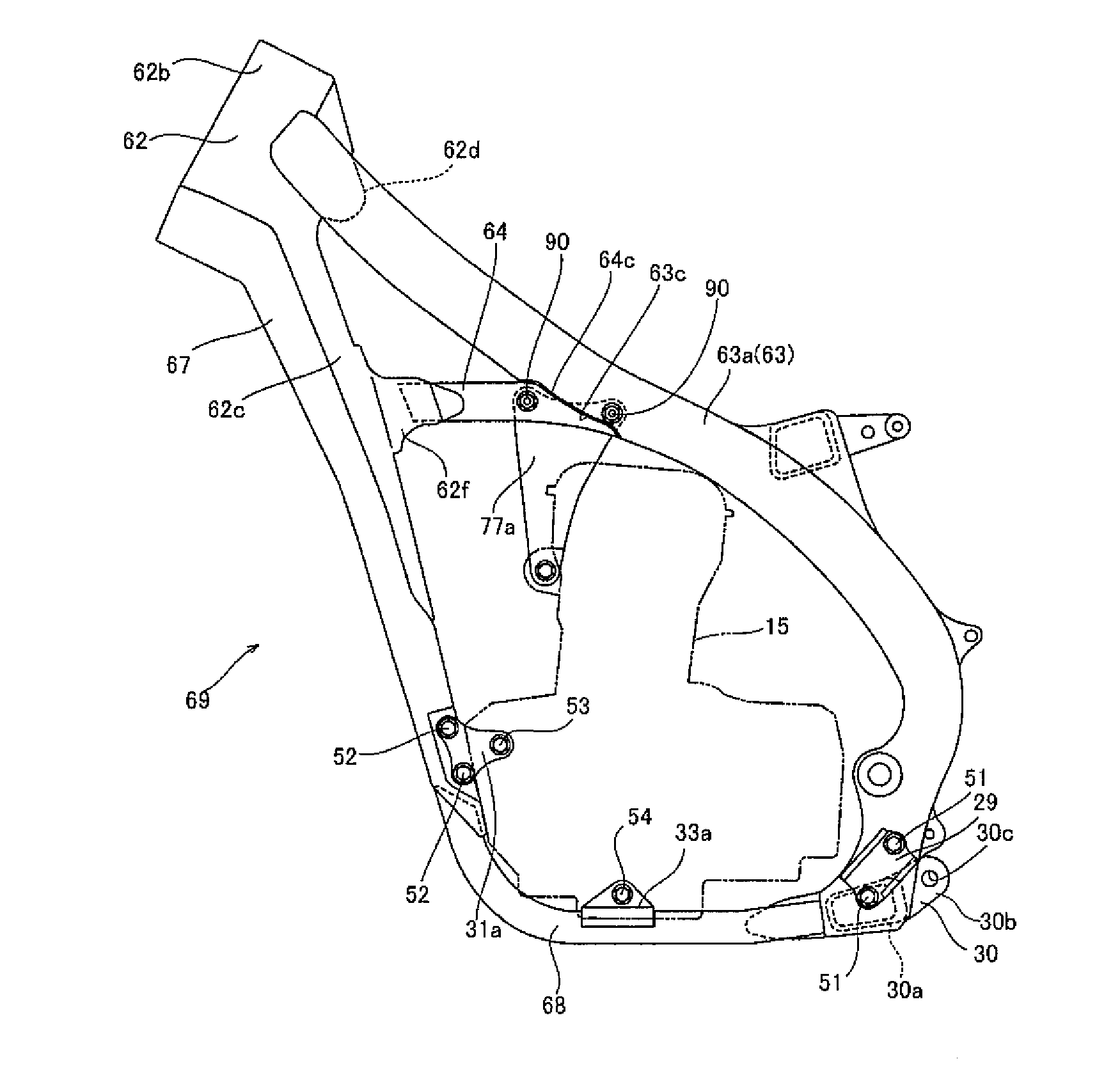
[0075]FIGS. 12 and 13 are explanatory views of a body frame of a motorcycle according to a second embodiment of the present invention. In the second embodiment, in contrast to the first embodiment, the front end of main frame 63 is connected directly to the rear section of cylindrical part 62b of head pipe 62.
[0076]As shown in FIG. 12 the front end of main frame 63 is directly connected to head pipe 62. Main frame 63 extends in a downwardly rearward direction and is an example of the “first frame” of the present invention.
[0077]Reinforcement member 64 is interposed between the rear of head pipe 62 and main frame 63. A front (one) end of reinforcement member 64 is connected to a part of head pipe 62 lower than the part where main frame 63 is connected, and a rear (other) end of reinforcement member 64 is connected to a middle part of main frame 63. Reinforcement member 64 is an example of the “second frame” of the present invention. A down tube 67 is disposed under head pipe 62. A lo...
PUM
 Abstract
Description
Claims
Application Information
 - R&D
- Intellectual Property
- Life Sciences
- Materials
- Tech Scout
- Unparalleled Data Quality
- Higher Quality Content
- 60% Fewer Hallucinations
Browse by: Latest US Patents, China's latest patents, Technical Efficacy Thesaurus, Application Domain, Technology Topic, Popular Technical Reports.
© 2025 PatSnap. All rights reserved.Legal|Privacy policy|Modern Slavery Act Transparency Statement|Sitemap|About US| Contact US: help@patsnap.com


