Magnetic means for detachably and rotatably connecting components in an audio speaker system

a technology for audio speakers and magnetic bodies, applied in the direction of transducer casings/cabinets/supports, flexible/turnable line connectors, coupling device connections, etc., can solve the problems of affecting the design of speaker systems and affecting the user's experience, so as to reduce the risk of damage, prevent the magnetic bodies from colliding with each other, and increase the surface area

Inactive Publication Date: 2009-12-01
PLASTOFORM INDS
View PDF2 Cites 82 Cited by
  • Summary
  • Abstract
  • Description
  • Claims
  • Application Information

AI Technical Summary

Benefits of technology

[0004]A front end of the conductive pin of the receiver module is spring-loaded to movably protrude outward from the front wall of the magnetic body of the receiver module, and a front end of the conductive pin of the transmitter module is securely disposed within the first electrically insulated layer of the transmitter module, thereby resulting in secure connection of the conductive pins when the transmitter module and the receiver module are connected with each other. Since the transmitter module is an active signal and / or power transmitter, the conductive pin of the transmitter module is completely enclosed within the first electrically insulated layer so as to prevent user or any external substance from coming into contact with the conductive pin and thus prevent the occurrence of short circuit.
[0006]The front end of the bracket extends inward towards the magnetic body so as to provide more surface area for magnetically connecting the transmitter module and the receiver module and concentrate the magnetic force at the front end of the bracket.
[0007]Accordingly, the second magnetically insulated layers each has a front wall which extends inward towards the magnetic bodies to insulate inner surface of the front end of the bracket from the front wall of the magnetic body and hold the magnetic bodies in place and thereby preventing the magnetic bodies from colliding with each other when the transmitter module and the receiver module connect with each other. Since the magnetic bodies are made of relatively brittle material, this could lower the risks of damaging the magnetic bodies when the transmitter module and the receiver module connect with each other.
[0009]The magnetic body of a most preferred embodiment takes the form of a neodymium-ferrite-boron magnet as neodymium-ferrite-boron can provide better magnetic strength. In other embodiments, it is also possible to use other magnetic materials such as ferrite.
[0015]When the receiver module and the transmitter module are connected to each other, the magnetic field of the magnetic bodies is conducted via the conductive plates to the brackets, thus the magnetic bodies, the conductive plates and the brackets in each of the upper part and the lower part form a substantially U-shaped magnet with the poles both lie at the front ends of the bracket and the magnetic body, thereby increasing the total magnetic force and achieving more secure connection between the transmitter module and the receiver module. Even when the power and signal source is activated, the user may still rotate the speaker in relation to the amplifier or vice versa to a preferred orientation without disrupting the connection between the receiver module and the transmitter module since the magnetic force keeps the receiver module and the transmitter module in contact with each other.

Problems solved by technology

The wires not only create a messy environment for the users, but also pose restrictions for designers in product design for speaker systems.

Method used


Image

  • Magnetic means for detachably and rotatably connecting components in an audio speaker system
  • Magnetic means for detachably and rotatably connecting components in an audio speaker system
  • Magnetic means for detachably and rotatably connecting components in an audio speaker system

Examples


Embodiment Construction

[0025]The present invention is further described in detail with the following embodiment and the accompanying drawings.

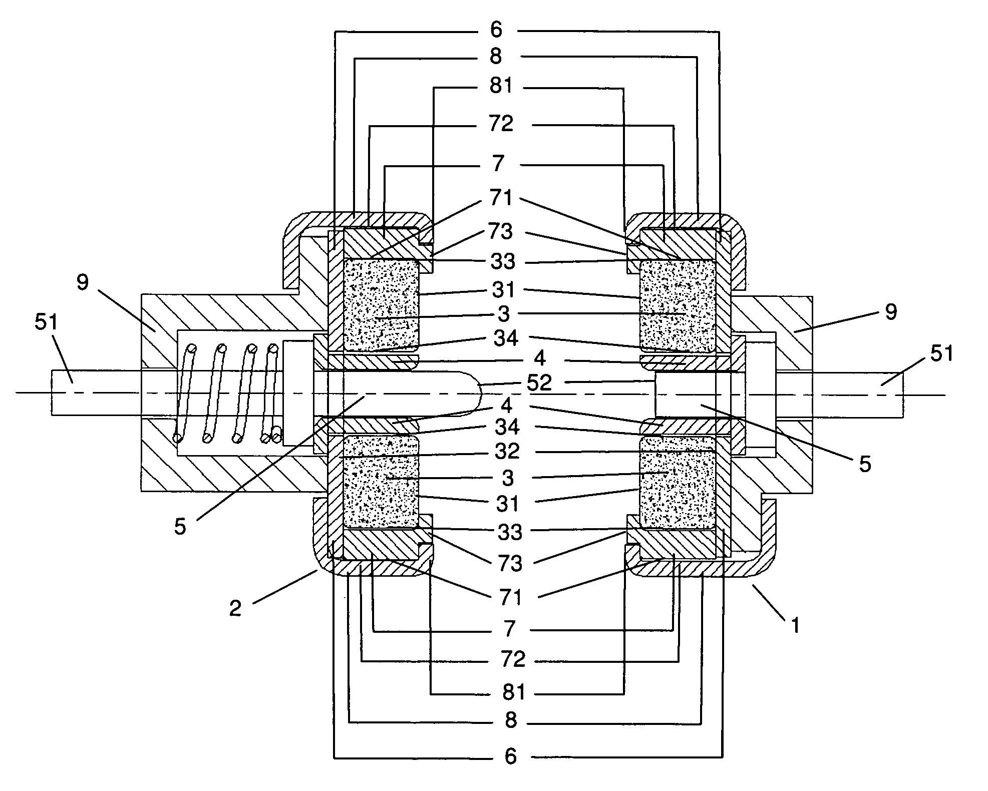
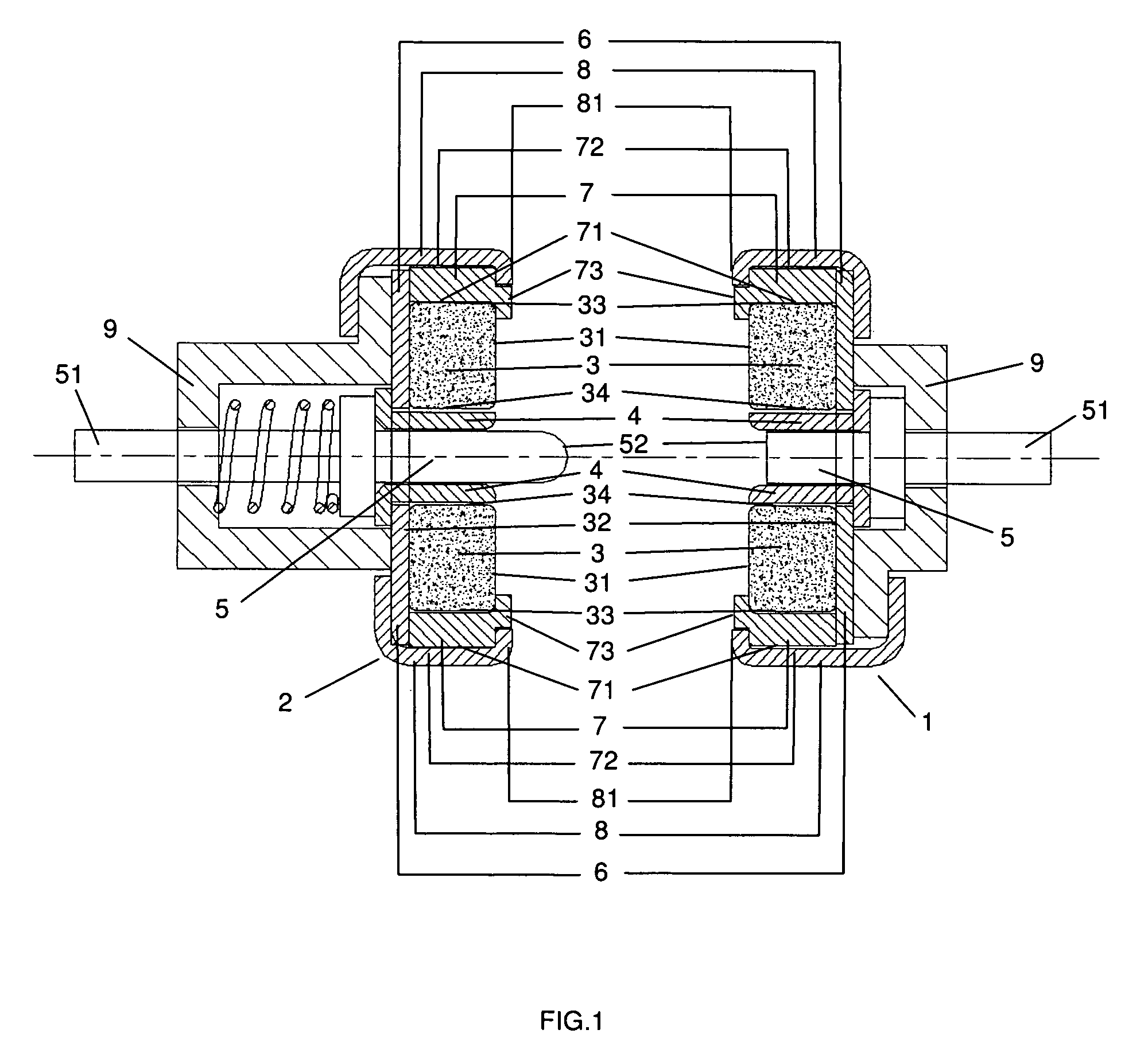
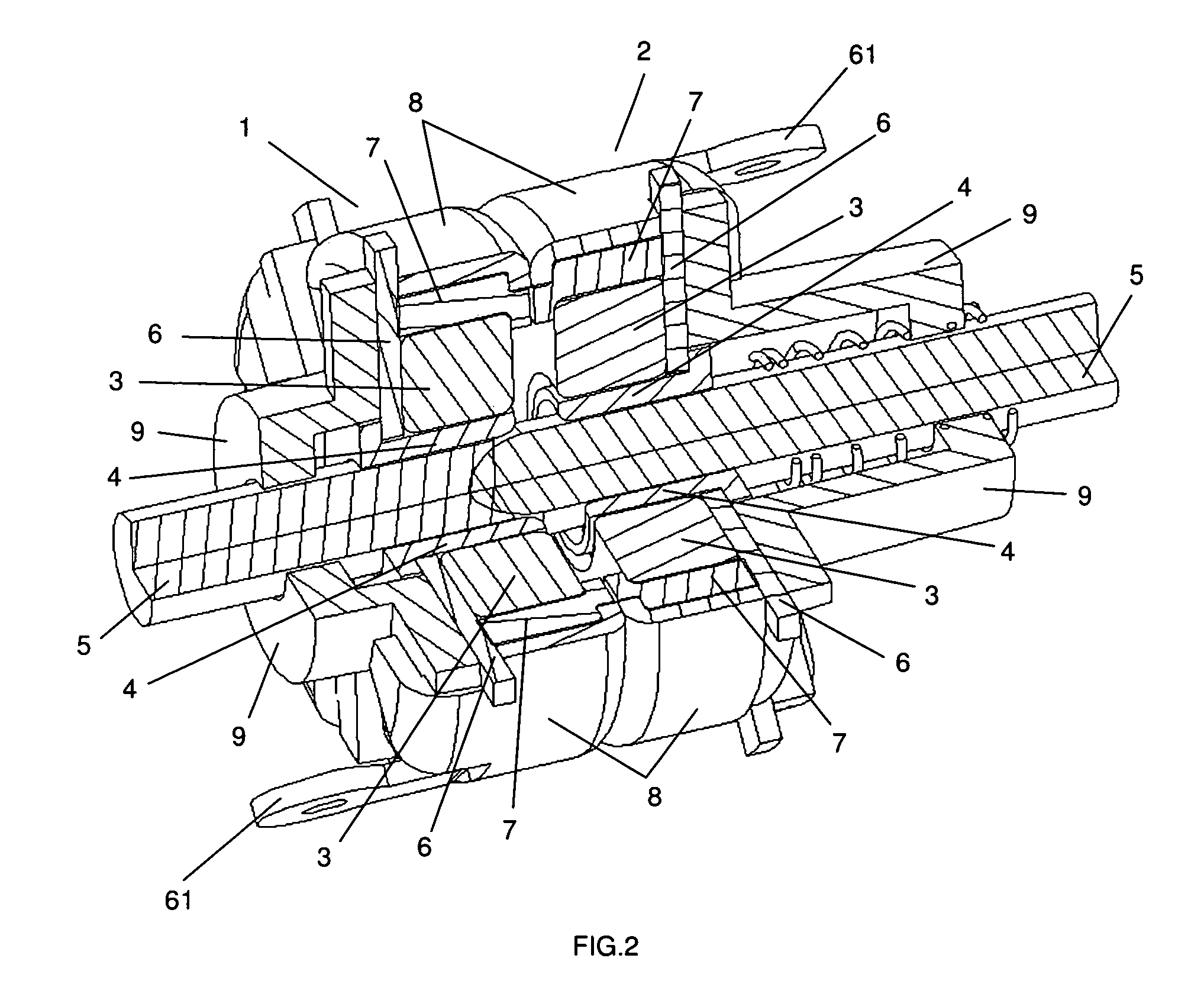
[0026]As illustrated in FIGS. 1 to 7, the present invention generally comprises a transmitter module 1 securely disposed in a power and / or signal source of the audio system and a corresponding receiver module 2 securely disposed in a power and / or signal receiving means of the audio system. Each of the transmitter module 1 and the receiver module 2 comprises a ring-shaped magnetic body 3, a first electrically insulated layer 4, a conductive pin 5, a conductive plate 6, a second magnetically insulated layer 7 and a bracket 8. The magnetic body 3 has a front wall 31, a rear wall 32, an outer wall 33 and an inner wall 34. The first electrically insulated layer 4 surrounds the inner wall 34 of the magnetic body 3. The conductive pin 5 passes through the first electrically insulated layer 4, and a rear end 51 thereof is electrically connected to a power and / or signal circ...


PUM


Abstract

Magnetic means for detachably and rotatably connecting components in an audio speaker system which comprises a transmitter module securely disposed in a power and / or signal source of the audio system and a corresponding receiver module securely disposed in a power and / or signal receiving means of the audio system, each of the transmitter module and the receiver module comprises a ring-shaped magnetic body, a first electrically insulated layer, a conductive pin, a conductive plate, a second magnetically insulated layer and a bracket, wherein the transmitter module has a first polarity at the front wall of the magnetic body thereof and a second polarity opposite to the first polarity at a front end of the bracket thereof, and the receiver module has the second polarity at the front wall of the magnetic body thereof and the first polarity at a front end of the bracket thereof, and the magnetic body and the bracket of the transmitter module have the same diameter as those of the receiver module, so that when the power and / or signal source is activated and the receiver module is connected to the transmitter module, the magnetic bodies and the brackets of transmitter module and the receiver module are rotatably attracted and connected to each other and power and / or signal is transmitted from the transmitter module to the receiver module via the conductive plates and the brackets thereof, and the conductive pins of the transmitter module and the receiver module connect with each other so that power and / or signal is transmitted from the transmitter module to the receiver module.

Description

BACKGROUND OF THE INVENTION[0001]Conventional audio speaker system generally comprises an amplifier, a left speaker and a right speaker. In some systems, the amplifier serves as the source of signal and power, and the left and the right speakers are connected to the amplifier by means of wires. In some systems, the left and the right speakers are each installed with an amplifier; in other systems, either the left or the right speaker is installed with an amplifier. In either case, the left and the right speakers are connected by means of wires. The wires not only create a messy environment for the users, but also pose restrictions for designers in product design for speaker systems.BRIEF SUMMARY OF THE INVENTION[0002]In view of the aforesaid disadvantages now present in the prior art, the object of the present invention is to provide a magnetic means for detachably and rotatably connecting components in an audio speaker system which replaces conventional wiring connections and thus ...

Claims


Application Information

Patent Timeline
Patent Type & Authority Patents(United States)
IPC IPC(8): H01R11/30
CPCH01R13/6205H04R1/02H01R35/00
Inventor TSE, KIN MAN MICHAEL
Owner PLASTOFORM INDS
Why Eureka
Try Eureka