Conditioning system for cooling and heating surfaces, particularly automobile seats

a technology for heating surfaces and cooling and heating surfaces, applied in the field of automobile seats, can solve the problems of dark leather seats, adversely affecting the feel of seats, and serious burns of skin, and achieve the effects of low porosity, low fluid loss over the service life, and low porosity

Inactive Publication Date: 2007-02-15
BIER CHRISTIAN +1
View PDF5 Cites 81 Cited by
  • Summary
  • Abstract
  • Description
  • Claims
  • Application Information

AI Technical Summary

Benefits of technology

[0031] In addition, the layers of plastic from which the fluid chamber system is formed should be as thin and flexible as possible, in order that the fluid chamber system can be emptied without difficulties and thereby collapses without any major folds, so that the deactivated temperature control mat cannot be felt or seen through the cushion covering. The layers of plastic may, for example, respectively have a thickness in the range from 10 μm to 1 mm, good results having been achieved for example with a layer thickness of 200 μm in each case.
[0032] For a low-maintenance system, it is advantageous to operate the fluid circuit in the fluid chamber system as a closed system. In this case, great value should be attached to the diffusion impermeability of the films of plastic used, in order that fluid losses over the service l...

Problems solved by technology

Cooling is necessary if car seats heat up under strong solar irradiation to high temperatures, which can lead to serious burns of the skin.
This problem arises in particular in the case of dark leather seats.
Because of the relatively rigid nature of the hoses or pipes, the system of lines undesirably presses through the seat covering and adversely affects the feel of the seat.
If the system of lines is arranged further in the interior of the seat to remedy this disadvantage, however, a significant reduction in efficiency occurs because of the poor heat transfer associated with the greater distance from the temperature-controlling surface.
It is disadvantageous, furthermore, that, in the case of the previously described systems, no moisture resulting for example from the perspiration of a person sitting on the surface is removed.
This may have the consequence on hot days of clothing becoming soaked with perspiration.
Although no...

Method used


Image

  • Conditioning system for cooling and heating surfaces, particularly automobile seats
  • Conditioning system for cooling and heating surfaces, particularly automobile seats
  • Conditioning system for cooling and heating surfaces, particularly automobile seats

Examples


Embodiment Construction

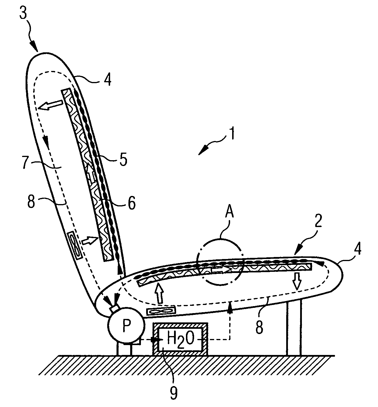
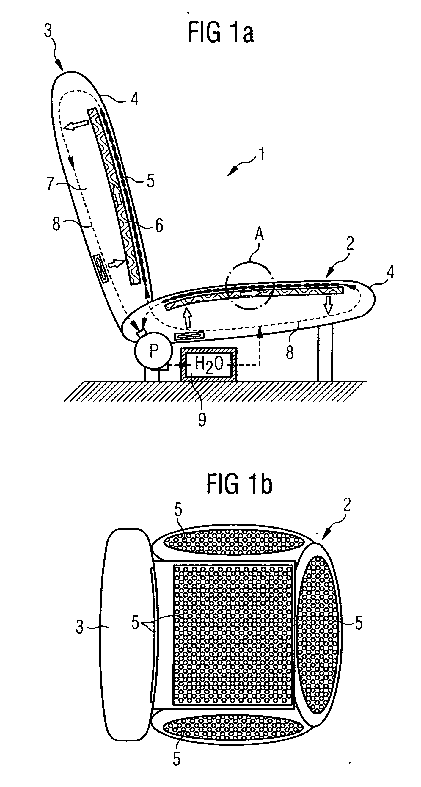
[0048]FIG. 1a shows a car seat 1 comprising a seat element 2 and a backrest element 3. Located under the seat coverings 4 both of the seat element 2 and of the backrest element 3 there is in each case a temperature control mat 5, which is kept at a distance from the cushion core 7 by a spacer structure 6. Water (H2O) is pumped as a temperature control fluid by means of a pump P from a storage tank 9 through the temperature control mat 5 through a system of fluid lines 8, which is represented as dashed lines with thin, black arrows, in order to control the temperature of (temperature control phase), in particular to cool (cooling phase), the seat covering 4 from the rear side. After completion of the temperature control phase, air is made to flow through the spacer structure 6 by means of a fan (white arrows), in order to assist the dissipation of perspiration moisture passing through the seat covering 4.

[0049]FIG. 1b shows the arrangement of the temperature control mat 5 in the car...


PUM


Abstract

A temperature control mat 5 is described, in particular for the rapid cooling of a vehicle seat covering 4. The temperature control mat comprises at least two interconnected thin films of plastic 5a, 5b, forming a fluid chamber system 10, and openings 11 distributed over the temperature control mat which penetrate through the temperature control mat 5. For temperature control, initially a temperature control fluid is directed through the fluid chamber system. Subsequently, the system is emptied and an air stream is directed through a spacing structure 6, in order to dissipate moisture passing through the openings 11.

Description

BACKGROUND OF THE INVENTION [0001] The invention relates to a temperature control system, which can be used for the rapid cooling and possibly also heating of surfaces—in particular of car seats. In addition, the invention relates to a seat and / or rest element, in particular with leather covering, and to a complete car seat, respectively fitted with such a temperature control system. Finally, the invention also relates to a temperature control mat for such a temperature control system and to a temperature control method for cooling and possibly heating a seat and / or rest element. [0002] It is known not only to heat but also to cool seats—in particular car seats. Cooling is necessary if car seats heat up under strong solar irradiation to high temperatures, which can lead to serious burns of the skin. This problem arises in particular in the case of dark leather seats. In general, the driver must wait until the seat has cooled down to a temperature comfortable for sitting, whether by ...

Claims


Application Information

Patent Timeline
IPC IPC(8): A47C31/00F28F7/00A47C7/74B60H1/00B60N2/56B60N2/90
CPCB60H1/00285B60H2001/00307B60N2/5657B60N2/5635B60N2/56
Inventor BIER, CHRISTIANKERSCHER, STEFAN
Owner BIER CHRISTIAN
Why Eureka
Try Eureka