Powered assisted liposuction and lipoinjection equipment

Inactive Publication Date: 2000-10-31
MICROAIRE SURGICAL INSTR
View PDF59 Cites 79 Cited by
  • Summary
  • Abstract
  • Description
  • Claims
  • Application Information

AI Technical Summary

Problems solved by technology

This technique requires significant effort on the part of the surgeon in terms of both the physical effort required to move the cannula back and forth, and the effort required to control the direction of movement of the cannula in order for fat tissue to be withdrawn only from specific areas of the patient's body.
The disadvantage of both these approaches is that they do not control the direction of liposuction, and can lead to withdrawing fat tissue unevenly, thus producing a lumpy surface upon completion of the surgery.
A disadvantage with each of these Swartz and Clark designs is that they tend to tear the tissue.
This can be problematic when working in

Method used


Image

  • Powered assisted liposuction and lipoinjection equipment
  • Powered assisted liposuction and lipoinjection equipment
  • Powered assisted liposuction and lipoinjection equipment

Examples


Embodiment Construction

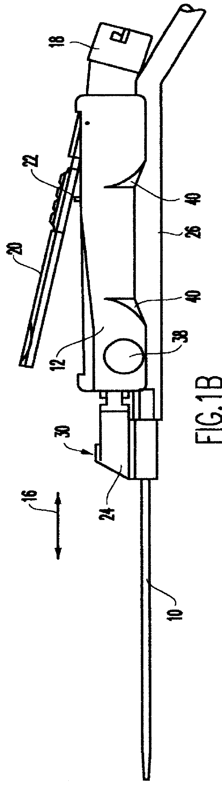
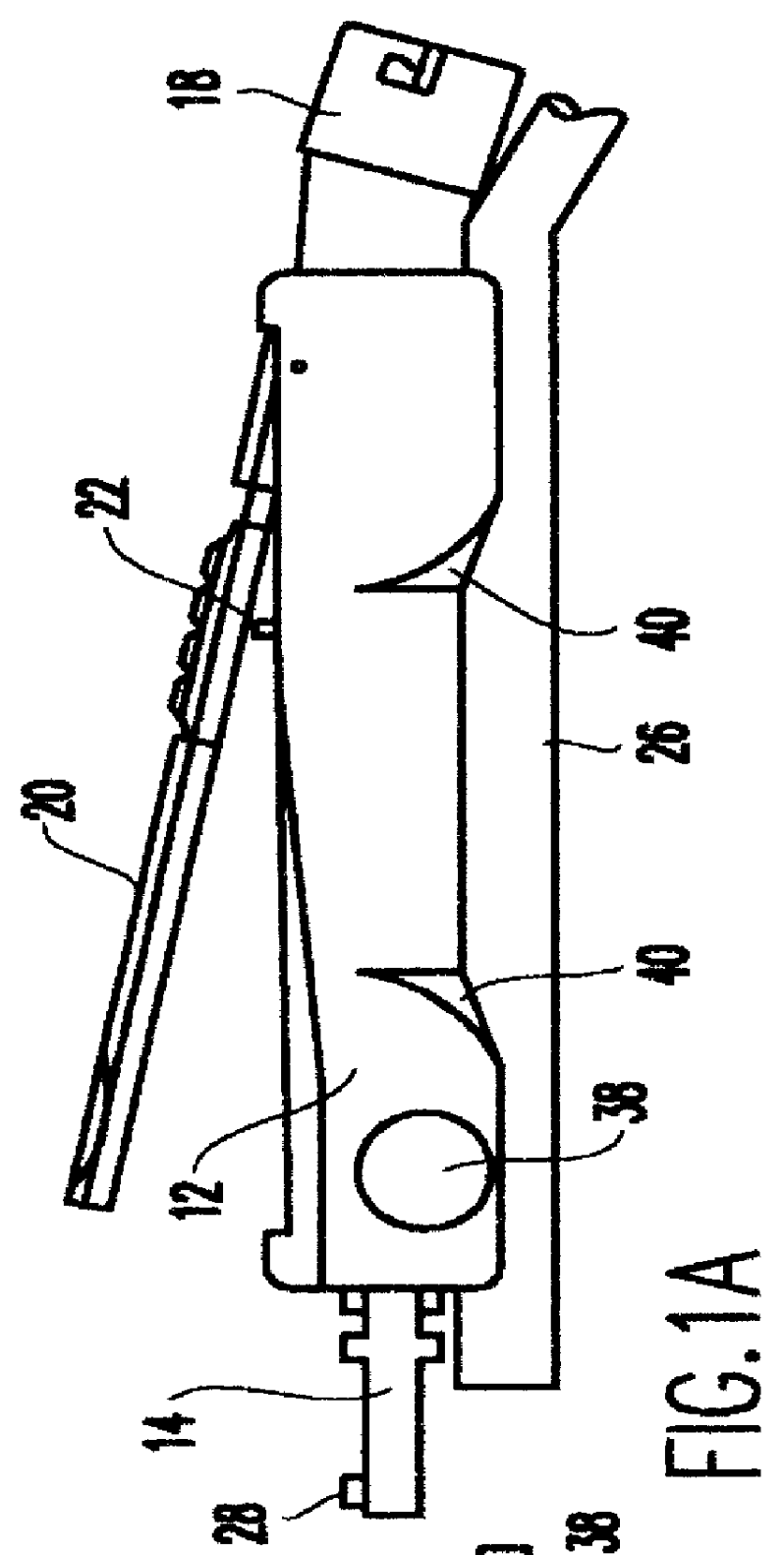
FIGS. 1a and 1b show the preferred embodiment of the power assisted liposuction / lipoinjection handpiece of the present invention. A cannula 10 is selectively connectable and disconnectable from a handle 12. The handle 12 includes a reciprocating member 14 which moves back and forth, as indicated by double headed arrow 16, in a reciprocating motion. In the preferred embodiment, the handle 12 includes a pneumatic drive assembly (not shown) and is connectable to a compressed air source by connector 18. An example of a suitable handle with internal pneumatic drive could be the MicroAire.RTM. 1400-100. However, it should be understood that any drive mechanism, including electrical, magnetic, etc., can be used to move the cannula 10 in a reciprocating motion 16.

The speed of reciprocation is preferably variable under the control of a lever 20 actuated button or switch 22, whereby complete depression of the lever 20 accelerates the reciprocation to its maximum speed, and partial depression ...


PUM


Abstract

A power assisted liposuction/lipoinjection handpiece includes a handle (12) which provides power to reciprocate a cannula (10) back and forth during surgery The cannula (10) can be connected to the handle (12) by a connector (24) that is affixed to, integrally formed with, or selectively joinable to a reciprocating member (14). Benefits in sterilization, distribution and surgical use can be realized when the cannula (10) and connector (24) are joined together, such that the surgeon merely needs to remove the cannula (10) from the package and connect it to a reciprocating member of a powered handle (12). The handle (12) may be configured such that the reciprocating member (14) is selectively detachable; thereby, allowing the handle (12) to be used for additional surgical procedures such as sawing or drilling. A vacuum hose (26) is connected to the cannula (10) such that vacuum pressure can be exerted through the cannula (10) for aspirating severed fat tissue. Preferably, the connector (24) radially offsets the cannula (10) from the reciprocating member (14) to a position which is axially in alignment with the vacuum hose (26); thereby avoiding bend regions and enhancing suction.

Description

DESCRIPTION1. Field of the InventionThe invention is generally related to powered hand tools used in surgical operations and, more particularly, to hand tools used in liposuction and lipoinjection procedures.2. Background DescriptionLiposuction is a well known surgical procedure for surgically removing fat tissue from selected portions of a patient's body. Current practice is to make an incision and then insert a cannula in the space occupied by fat tissue. The cannula is then moved in such a manner as to mechanically break up the fat tissue. While moving the cannula, pieces of the fat tissue are aspirated from the space through the cannula by vacuum pressure from a syringe or pump. This technique requires significant effort on the part of the surgeon in terms of both the physical effort required to move the cannula back and forth, and the effort required to control the direction of movement of the cannula in order for fat tissue to be withdrawn only from specific areas of the patie...

Claims


Application Information

Patent Timeline
IPC IPC(8): A61B17/32A61M1/00A61B17/00A61B17/22A61M37/00
CPCA61B17/32002A61M1/0086A61M2202/08A61M1/86
Inventor MOZSARY, PETER G.FARD, MIKEPASCALOFF, JOHN
Owner MICROAIRE SURGICAL INSTR
Why Eureka
Try Eureka