
Outlet power strip with remote control

a technology of remote control and power strip, which is applied in the direction of relays, contact mechanisms, coupling device connections, etc., can solve the problems of inflated electric utility bills, waste of electricity, and electricity drawn by household electronic devices, and achieve the effect of saving electricity and economic gain for users

Inactive Publication Date: 2012-01-31
SARULLO FR
View PDF12 Cites 30 Cited by
  • Summary
  • Abstract
  • Description
  • Claims
  • Application Information

AI Technical Summary

Benefits of technology

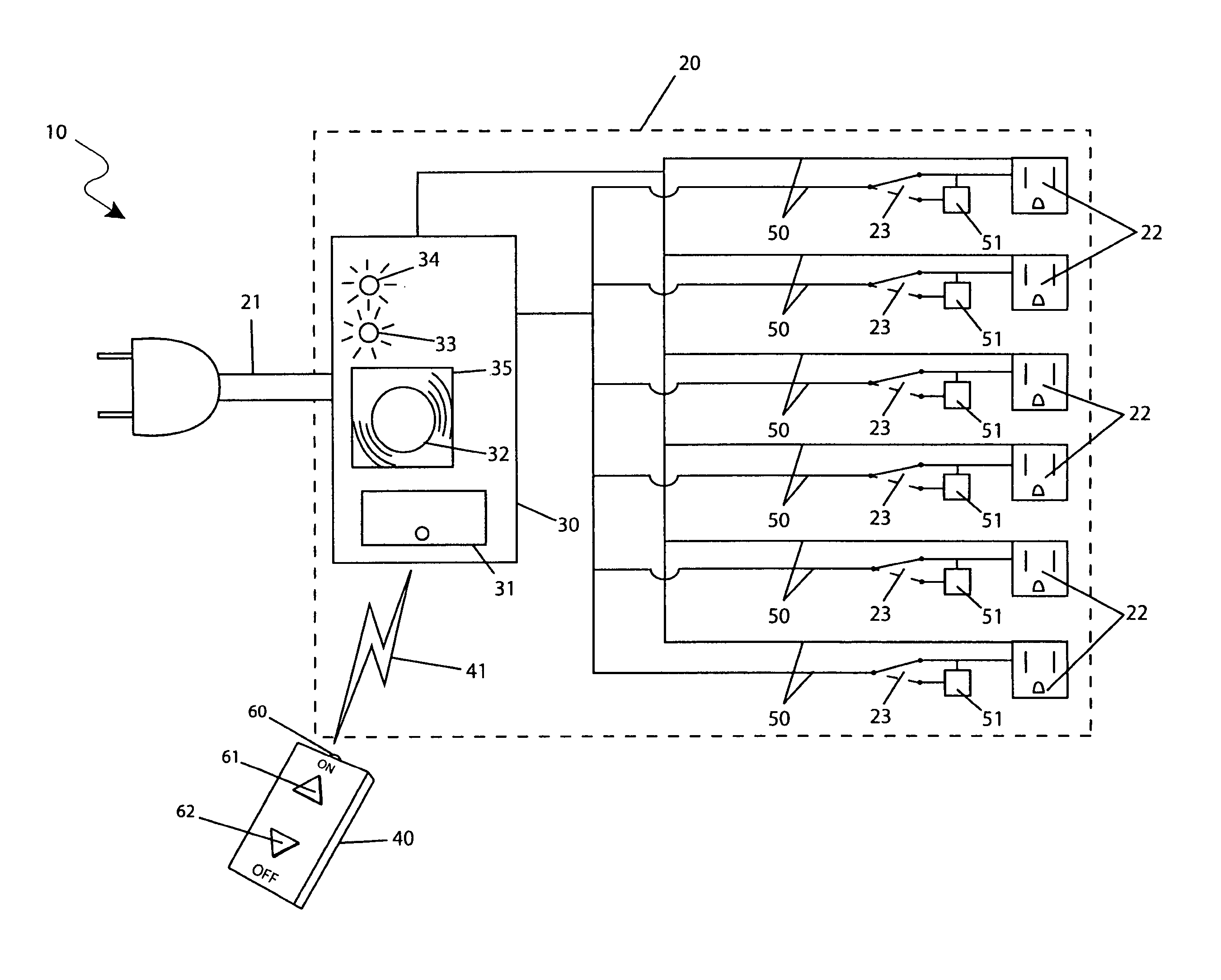
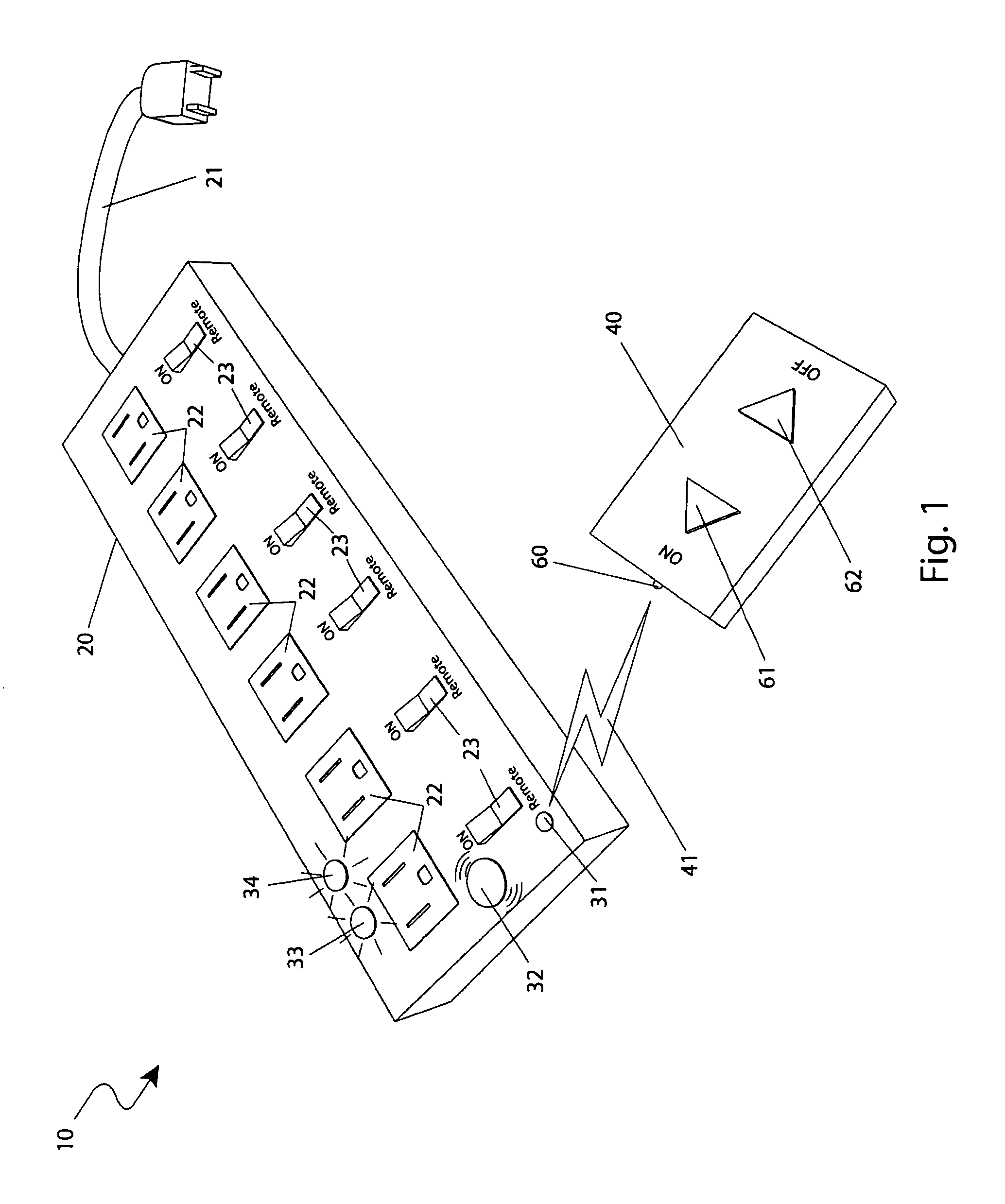
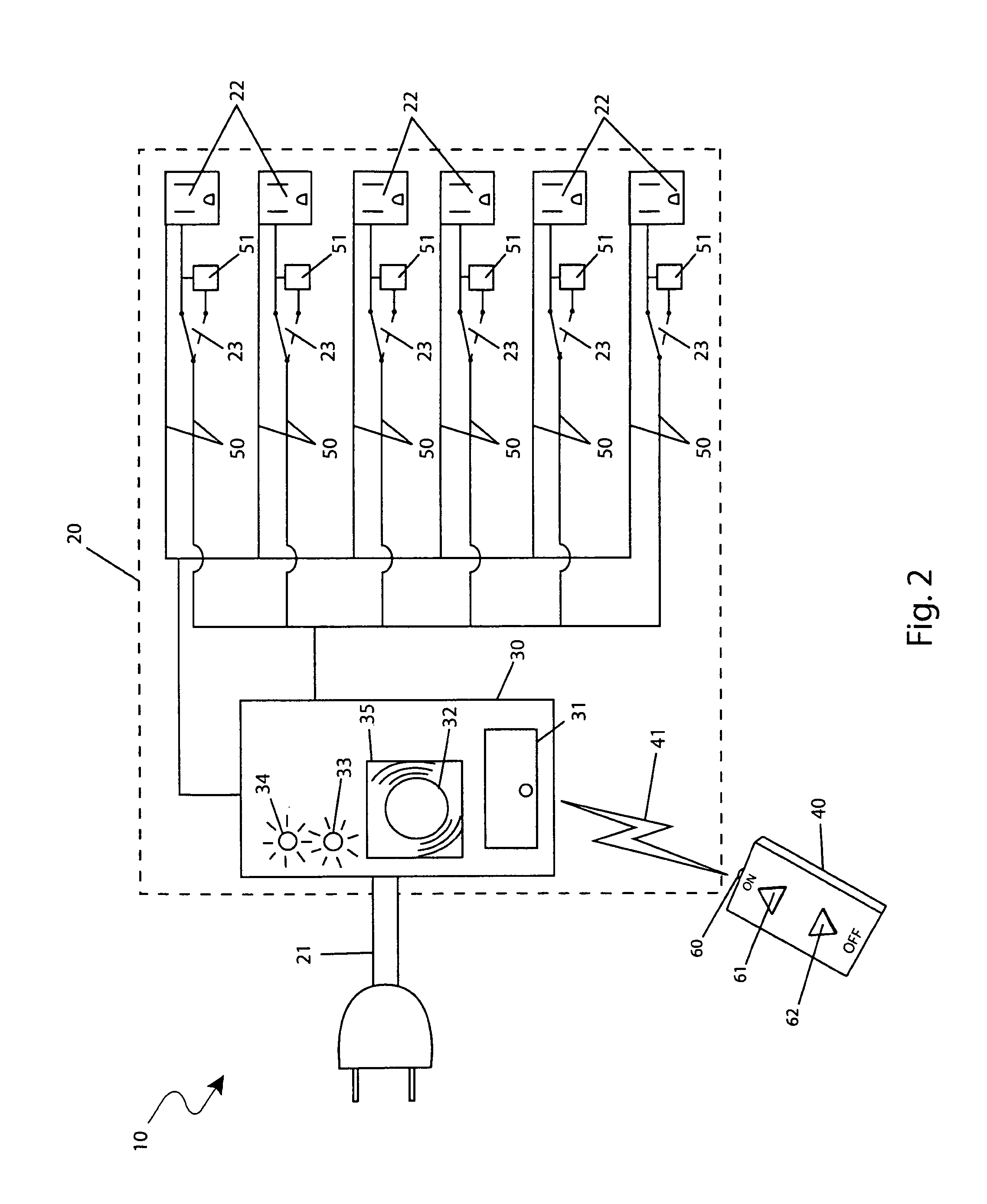
[0012]Another object of the present invention is to provide an outlet power strip with remote control which enables a user to turn on and off all the electrical receptacles of the power strip from a remote location.
[0013]Another object of the present invention is to provide an outlet power strip with remote control that enables external electrical devices to be de-energized when not in use, thus saving electricity and providing an economic gain for the user.
[0016]Another object of the present invention is to provide an outlet power strip with remote control that enables the power strip to be located in out of sight locations and provides a means to communicate with the power strip that does not require line of sight.
[0020]The present invention provides a method of utilizing the device that allows users of power strips the ability to quickly and easily turn power strips on and off without the requirement of touching or even seeing them in a manner which is quick, easy and effective.

Problems solved by technology

Additionally, many of the current household electronic devices draw electricity even when turned off while in a “standby” configuration.
This can lead to wasted electricity usage and inflated electric utility bills.
While these devices may fulfill their respective, particular objectives, each suffers from one or more disadvantage.
This is not always easy when such strips are under desks, behind furniture or in the back of cabinets.
This typically forces a user to access the power control switch and perhaps leave the device on thus wasting power and not utilizing the power strip to its full potential.
One solution to this is to simply move the power strip to a more accessible location, where it may be unsightly.
However, these solutions still limit control of the power supply to locations adjacent to the power strip and require the user to physically engage the power strip.

Method used


Image

  • Outlet power strip with remote control
  • Outlet power strip with remote control
  • Outlet power strip with remote control

Examples


Embodiment Construction

[0043]The best mode for carrying out the invention is presented in terms of its preferred embodiment, herein depicted within FIGS. 1 and 2. However, the invention is not limited to the described embodiment and a person skilled in the art will appreciate that many other embodiments of the invention are possible without deviating from the basic concept of the invention, and that any such work around will also fall under scope of this invention. It is envisioned that other styles and configurations of the present invention can be easily incorporated into the teachings of the present invention, and only one particular configuration shall be shown and described for purposes of clarity and disclosure and not by way of limitation of scope.

[0044]The terms “a” and “an” herein do not denote a limitation of quantity, but rather denote the presence of at least one of the referenced items.

[0045]The present invention describes an outlet power strip with remote control (herein described as the “ap...


PUM


Abstract

An electrical power strip with multiple outlets capable of being controlled by a wireless remote controller is herein disclosed. The handheld wireless controller is used to control the operation of the power strip via a radio frequency (RF). As such, the power strip is particularly advantageous for use under desks, behind shelves and in otherwise inaccessible locations, as the user can turn the entire power strip on and off without reaching it. Additionally, individual bypass switches are provided for each receptacle to turn it on permanently.

Description

RELATED APPLICATIONS[0001]The present invention was first described in and claims the benefit of U.S. Provisional Application No. 61 / 189,458 filed on Aug. 20, 2008, the entire disclosures of which are incorporated herein by reference.FIELD OF THE INVENTION[0002]The present invention relates generally electrical outlet power strips and, more particularly, to an electrical power supply strip capable of being controlled by, a wireless remote controller.BACKGROUND OF THE INVENTION[0003]In recent years the presence of electrical and electronic devices in our lives has proliferated. It is not uncommon to have dozens of such devices in ones home. In many cases such as with personal computer systems, entertainment systems, recharging areas, and the like, it is not uncommon to have many devices competing for one (1) electrical outlet. Additionally, many of the current household electronic devices draw electricity even when turned off while in a “standby” configuration. This can lead to waste...

Claims


Application Information

Patent Timeline
IPC IPC(8): H01H3/00H01H9/54H01H33/59H01H85/46H01H47/00
CPCH01R25/006H01H2300/03H01R13/6683Y04S20/14Y02B90/224Y10T307/469Y10T307/937Y02B90/20
Inventor SARULLO, FRANK
Owner SARULLO FR
Learn More