Switched mode power supply

a power supply and switch mode technology, applied in the direction of generator/motor, dc-ac conversion without reversal, machines/engines, etc., can solve the problem of negligible effect of switching mode power supply efficiency, and achieve the effect of keeping the mechanical loading of the blade low

Inactive Publication Date: 2012-01-31
SIEMENS AG
View PDF30 Cites 10 Cited by
  • Summary
  • Abstract
  • Description
  • Claims
  • Application Information

AI Technical Summary

Benefits of technology

[0015]The advantage of a piezoelectric fan for use in a switched mode power supply lies in the mode of operation: the air flow generated can be guided in a targeted manner onto the components to be cooled, with the air throughflow in total remaining low and therefore no contamination occurring by means or air-borne dirt particles. Moreover, a piezoelectric fan consumes only a very small amount of energy, so the effect on the efficiency of the switched mode power supply is negligibly low.
[0027]It is also advantageous if those power values, which are detected in the case of undamaged, freely-swinging blades of the at least one piezoelectric fan, are programmed into the microcontroller for predefined excitation frequencies and associated tolerance values (to take account of changed environmental conditions), and if the frequency of the control signal is altered at predefined intervals during operation, so altered resonance frequencies are detected. The microcontroller therefore immediately detects if the resonance frequency of the piezoelectric fan changes beyond the tolerance limits, and this can usually be attributed to a crack in the blade or to contact with a foreign body. The pre-requirements are therefore established that the switched mode power supply should be switched off if the piezoelectric fan is in a critical state, before components of the switched mode power supply incur damage, and the result can be signaled to maintenance or operating staff.

Problems solved by technology

Moreover, a piezoelectric fan consumes only a very small amount of energy, so the effect on the efficiency of the switched mode power supply is negligibly low.

Method used


Image

  • Switched mode power supply
  • Switched mode power supply
  • Switched mode power supply

Examples


Embodiment Construction

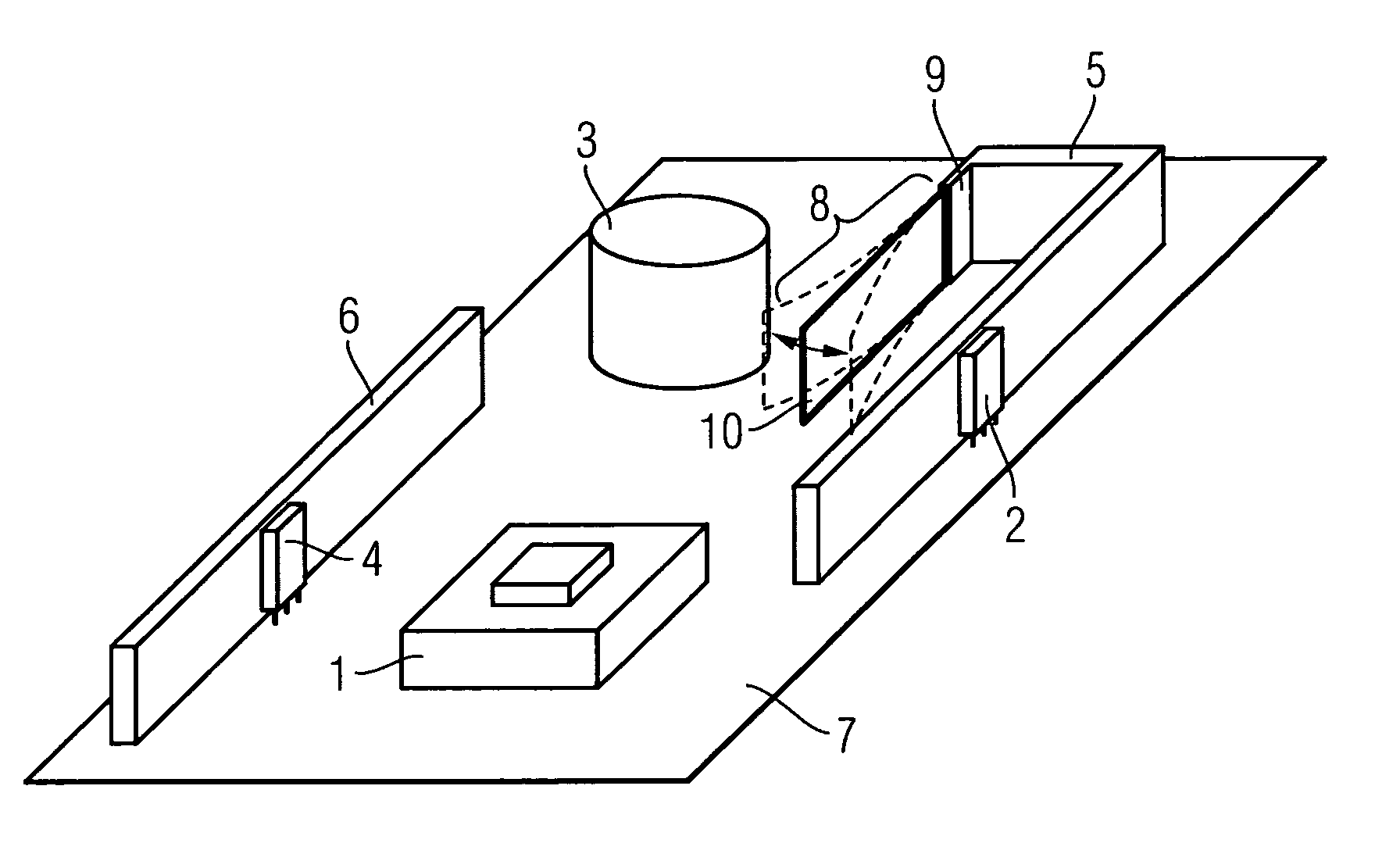
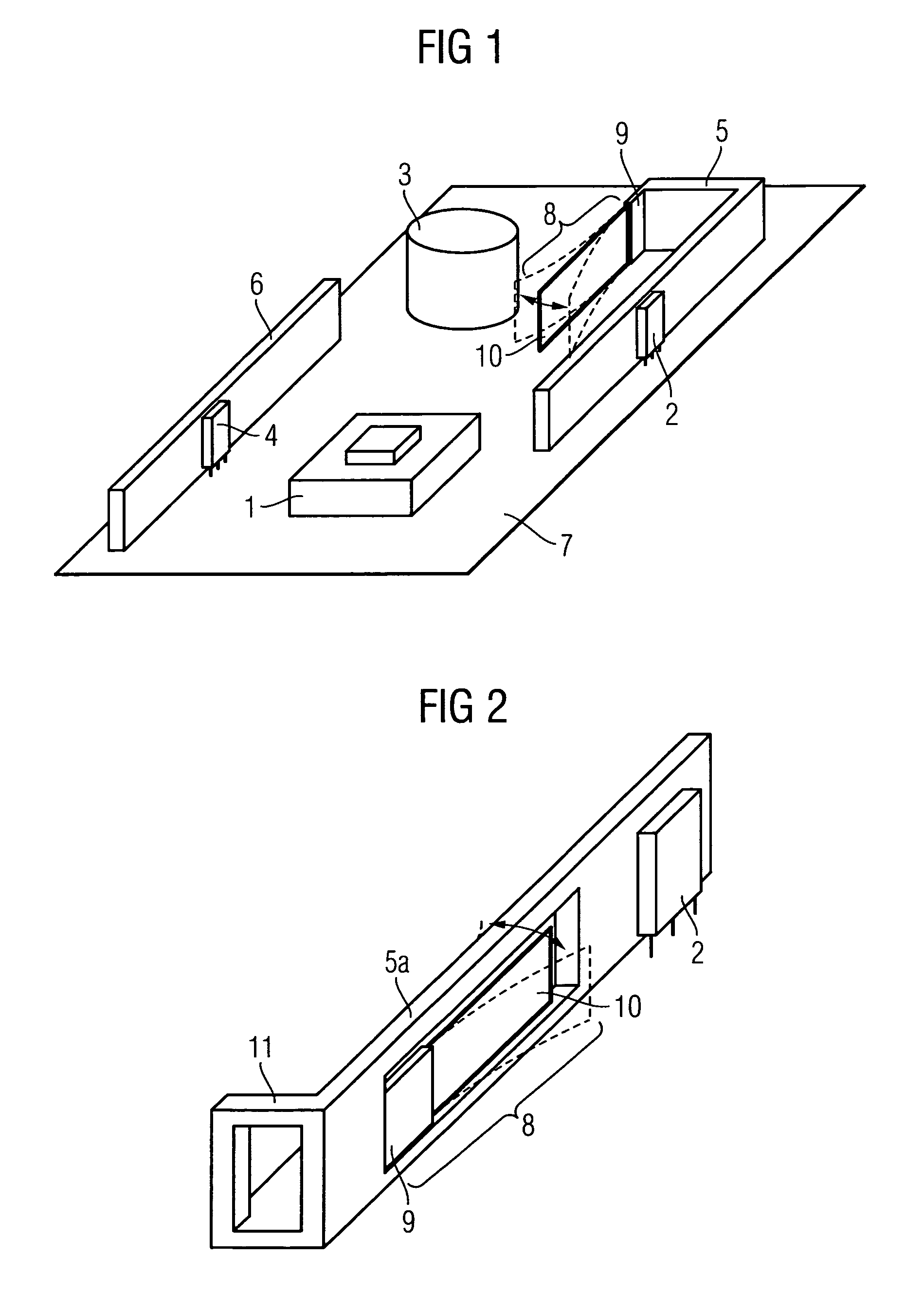
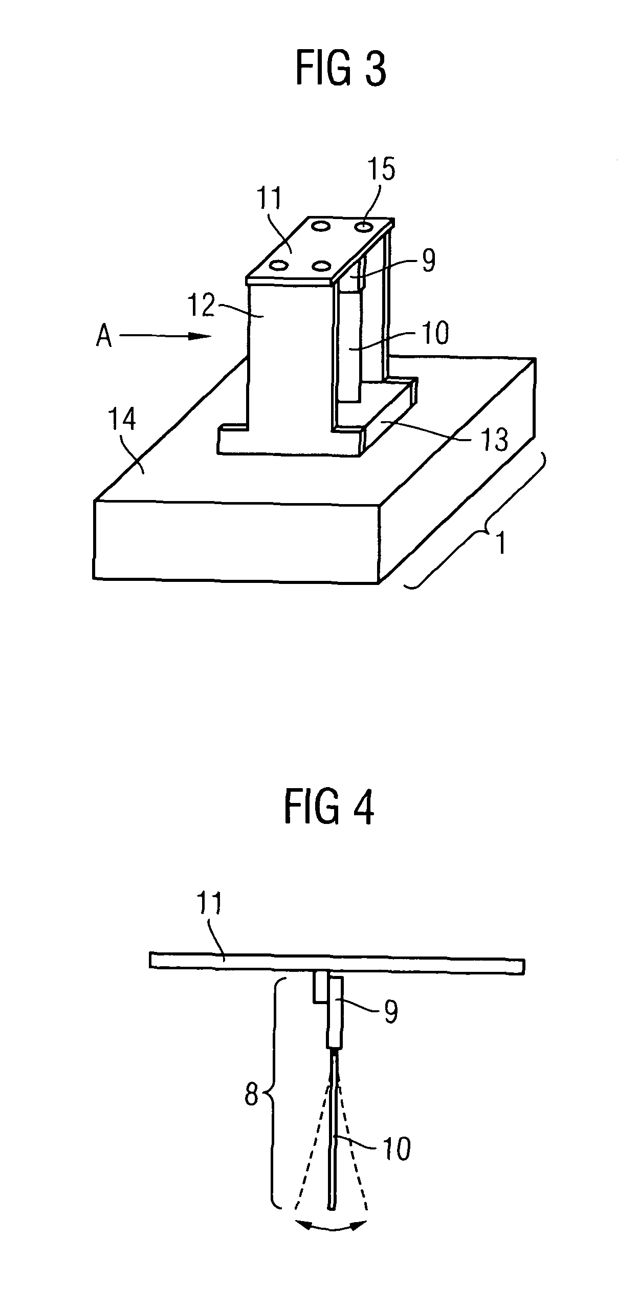
[0040]FIG. 1 shows, in a highly simplified manner, the physical arrangement of the heat-generating elements of a switched mode power supply. A transformer 1, a primary-side switching element 4, a capacitor 3 (for example an electrolyte capacitor) and a secondary-side diode 2 are arranged on a substrate 7. The secondary-side diode 2 is thermally coupled to a first heat sink 5 and the primary-side switching element 4 to a second heat sink 6. The first heat sink 5 also acts as a receiver for the holder 9 of a piezoelectric fan 8.

[0041]With its freely swinging end the blade 10 of the piezoelectric fan 8 points in the direction of the transformer 1. The transformer 1 is therefore located in the main flow direction of the air flow generated by the piezoelectric fan 8. As the piezoelectric fan 8 generates a widely-dispersing air flow the elements arranged to the side of the piezoelectric fan 8 are also ventilated and therefore cooled.

[0042]When configuring the casing (not shown) of the swi...


PUM


Abstract

A switched mode power supply is provided. The switched mode power supply includes a transformer, which includes at least one primary winding connected to a DC voltage via a switching element and a secondary winding connected to a load via a rectifier circuit including at least one diode, and at least one piezoelectric fan which generates an air flow at the transformer and / or at the switching element and / or at the diode. The air flow produced can be guided in a targeted manner onto the components to be cooled, with the air flow remaining low and therefore, no contamination by air particles arises.

Description

CROSS REFERENCE TO RELATED APPLICATIONS[0001]This application is the US National Stage of International Application No. PCT / EP2007 / 057038, filed Jul. 10, 2007 and claims the benefit thereof. The International Application claims the benefits of German application No. 10 2006 046 982.8 DE filed Oct. 4, 2006, both of the applications are incorporated by reference herein in their entirety.FIELD OF INVENTION[0002]The invention relates to a switched mode power supply with a transformer, which comprises at least one primary winding, which can be connected to a DC voltage via a switching element and which comprises at least one secondary winding, which can be connected to a load via a rectifier circuit comprising at least one diode.BACKGROUND OF INVENTION[0003]Switched mode power supplies are known in a wide variety of developments and are used to connect electrical loads to a power grid or to a power source. A distinction is made for example between switched mode power supplies, which oper...

Claims


Application Information

Patent Timeline
Patent Type & Authority Patents(United States)
IPC IPC(8): H01L41/08
CPCH01L23/467H05K7/20172H05K7/20909F04D33/00H02M3/28H01L2924/0002H01L2924/00H02M7/48H05K7/20
Inventor EICHHORNER, BERNHARDSCHWEIGERT, HARALD
Owner SIEMENS AG
Why Eureka
Try Eureka