Methods and apparatus for sound production

a technology of sound production and sound, applied in the direction of electrical transducers, earpiece/earphone attachments, transducer details, etc., can solve the problems of unintended sounds and sound effects, unhealthy sound pressure on the middle ear, and reducing the quality of audio production

Active Publication Date: 2012-02-07
PENG YAN RU
View PDF32 Cites 16 Cited by
  • Summary
  • Abstract
  • Description
  • Claims
  • Application Information

AI Technical Summary

Problems solved by technology

First, it is noted that such an earbud 1200 creates an unhealthy amount of sound pressure on the middle ear 1216. In particular, not only does the speaker direct sound at the structures of the middle ear, but sound pressure waves reflected inside the ear have nowhere to escape, and continue to echo inside the ear canal 1108 and can repeatedly strike the middle ear 1216. Not only is this unhealthy, but it further creates unintended sounds and sound effects which reduce the quality of audio production.
Second, such an earbud 1200, by fully occluding the ear canal 1108, blocks outside sounds 1204 from entering the ear. This presents a safety risk, as important outside sounds such as traffic sounds and emergency alarms can not be heard when the earbuds 1200 are in use.
Third, such an earbud 1200 is necessarily uncomfortable to a large number of users, since ear canal diameter varies from individual to individual in a large way, while earbuds are often sold in only one or two sizes.
It should be noted that other headphones, such as earmuff-style headphones or earcap-style headphones, pose similar disadvantages, including at least full occlusion of the ear canal, an echo surface for sound waves which are reflected at the middle ear, and the unhealthy aiming of sound waves directly at the structures of the middle ear.

Method used


Image

  • Methods and apparatus for sound production
  • Methods and apparatus for sound production
  • Methods and apparatus for sound production

Examples


Embodiment Construction

[0026]Initially, it is noted that aspects of the presently disclosed sound production devices and methods are disclosed is U.S. Patent Application Publication Number 2007 / 0160245, corresponding to U.S. patent application Ser. No. 11 / 605,418, of which the present application claims benefit, and which is incorporated herein by reference in its entirety. The present application adds further details and embodiments. In the present application, like numbers correspond to like elements between the present application and the aforesaid U.S. patent application.

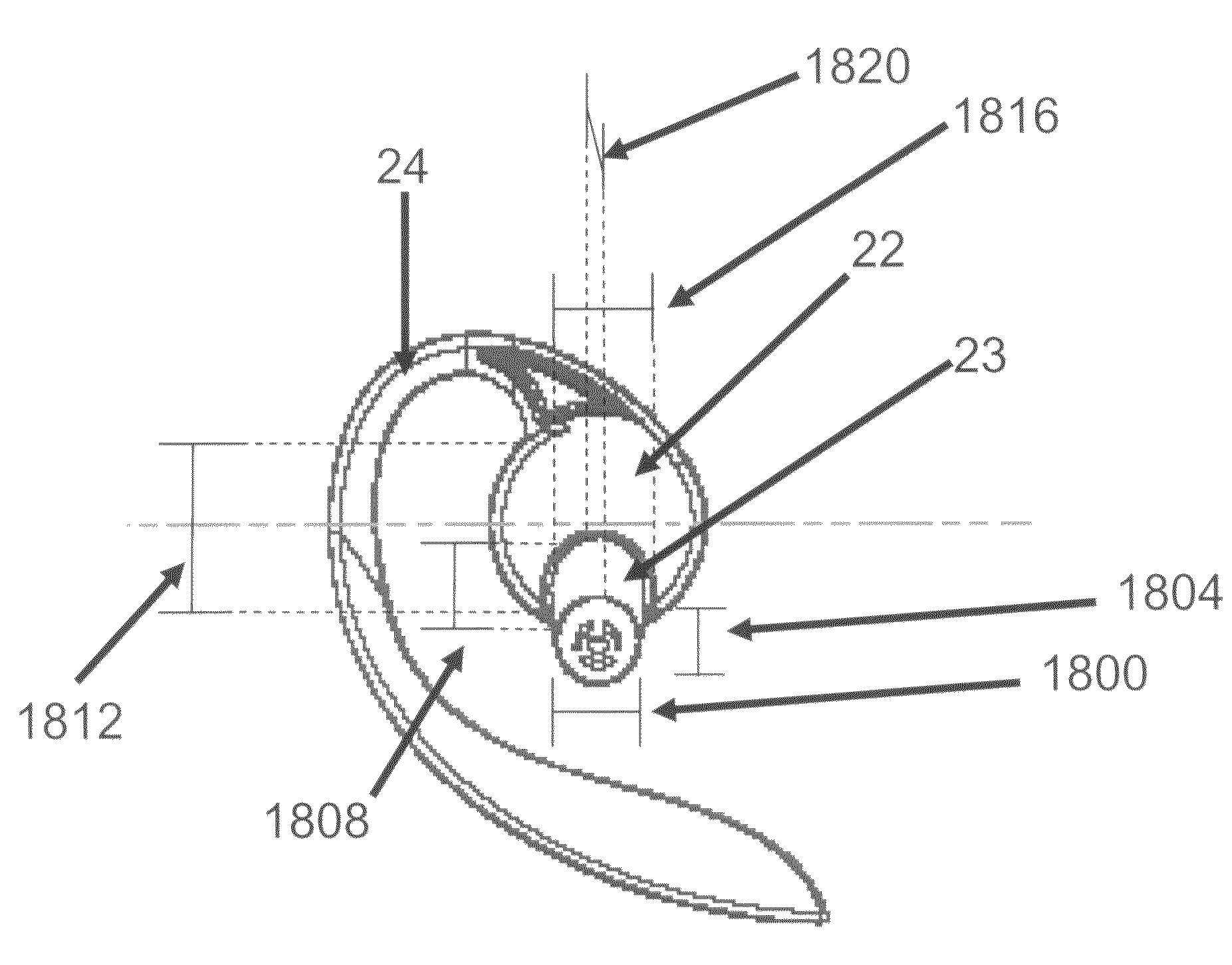
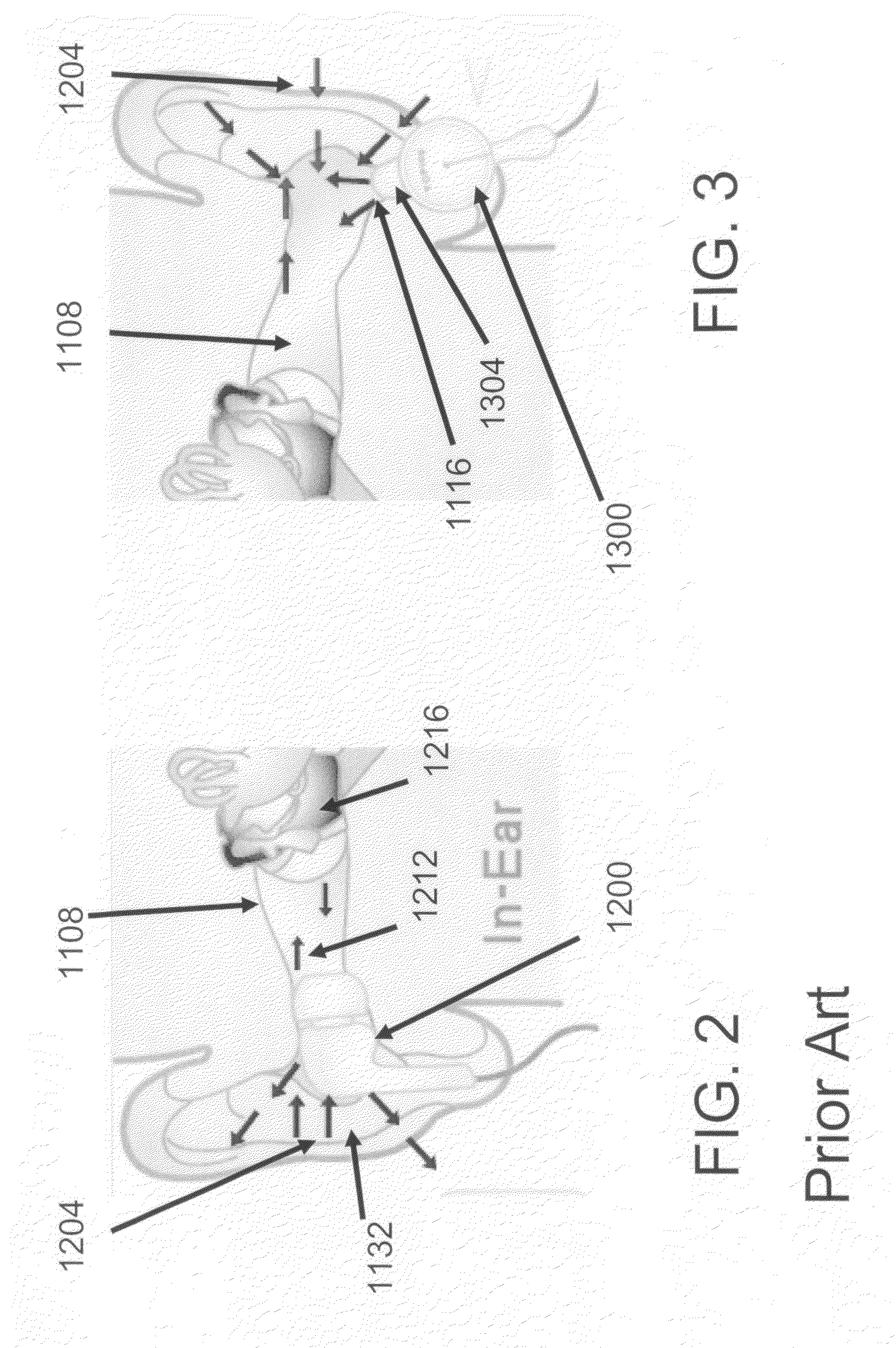
[0027]FIG. 3 shows one aspect of a sound production device 1300 according to the present disclosure. Sound production device 1300 directs sound waves through a tube 1304 which rests in an intertragic notch 1116 of a human external ear. Other locations are described in the following paragraphs with reference to the remaining figures. Although only one ear is shown, it is understood that two devices 1300 are typically used, on in each e...


PUM


Abstract

Electrical signals corresponding to sound are received at a wire, and sound is generated at a speaker connected to the wire. The sound is resonated in a cavity of a shell housing the speaker, and then passed along a transmission tube toward a pinna of a user's ear without directing the sound directly toward the user's ear canal.

Description

CROSS-REFERENCE TO RELATED APPLICATIONS[0001]This application is a Continuation In Part of U.S. patent application Ser. No. 11 / 605,418, filed Nov. 29, 2006 now abandoned, the contents of which are hereby incorporated by reference in their entirety.BACKGROUND OF THE INVENTION[0002]1. Field of the Invention[0003]The present disclosure relates to methods and apparatuses for sound production, and in particular, to methods and apparatuses for producing sound at the ear of the user.[0004]2. Related Art[0005]FIG. 1 shows a diagram of a typical human ear. The outer ear, or pinna, is an irregularly concave cartilaginous member comprised of a number of eminences and depressions which give each ear a distinct shape and form. The helix 1100 is the curved outer rim of the ear; below the helix 1100 is the antihelix 1124, a curved prominence which describes a curve around the concha, a deep cavity containing the entry to the ear canal 1108. The concha is divided into two parts, the upper and lower...

Claims


Application Information

Patent Timeline
Patent Type & Authority Patents(United States)
IPC IPC(8): H04R1/20
CPCH04R1/1075H04R1/2803H04R1/345
Inventor PENG, YAN-RU
Owner PENG YAN RU
Why Eureka
Try Eureka