Headphone device

a headphone and headphone technology, applied in the direction of transducer details, electrical transducers, electrical apparatus, etc., can solve the problems of low wearability of the device, pain for users to wear the device for a long time, and difficulty for users to wear the device, so as to achieve comfortable feeling, high stability, and without giving a feeling of pain

Inactive Publication Date: 2011-01-13
SONY CORP
View PDF3 Cites 16 Cited by
  • Summary
  • Abstract
  • Description
  • Claims
  • Application Information

AI Technical Summary

Benefits of technology

[0017]Thus, the headphone device can be mounted to any auricle regardless of its size and shape by supporting it at two points, i.e., the driver unit and the end of the arm. Therefore, the device can be worn by any user with a comfortable feel and high stability and without giving a pain.
[0018]According to the embodiment of the invention, since the headphone device can be mounted to any auricle regardless of its size and shape by supporting it at two points, i.e., the driver unit and the end of the arm, the device can be worn by any user with a comfortable feel and high stability and without giving a pain.

Problems solved by technology

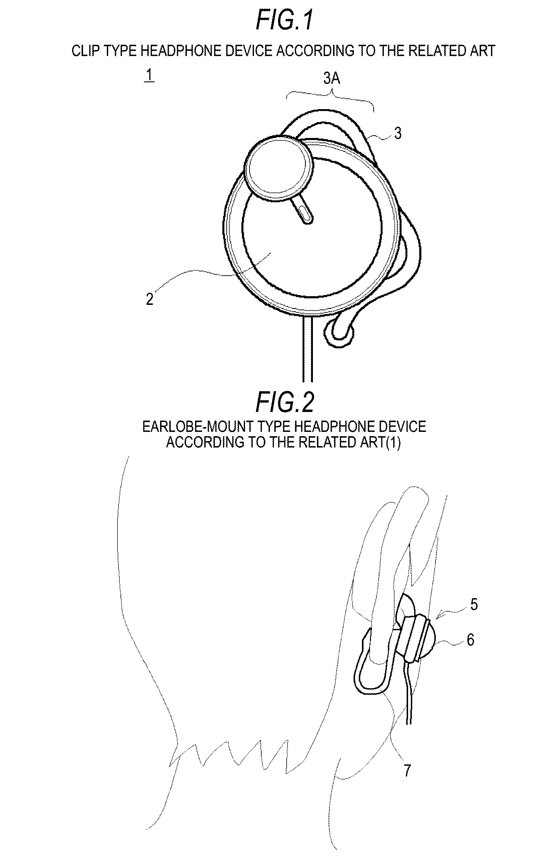
The above-described clip type headphone device 1 (FIG. 1) exerts a pressure to an upper part of an auricle because the device is constructed to sandwich the upper part of the auricle between the main body 2 and the upper part 3A of the hanging type earpiece 3, and the device therefore has a problem in that it can be painful for a user to wear the device for a long time.
Therefore, the clip type headphone device 1 has a problem in that it is difficult to wear the device for a user whose auricles do not fit the position of the upper part 3A of the hanging type earpiece 3 and in that the wearability of the device consequently becomes low because of loads imparted to an auricle itself.
Then, a problem arise in that the device can no longer sufficiently function as a headphone and can become a mere decoration.
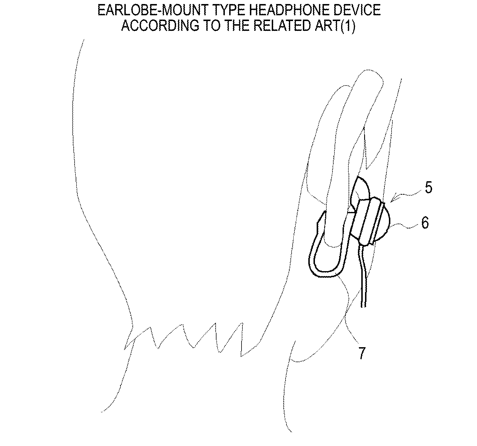
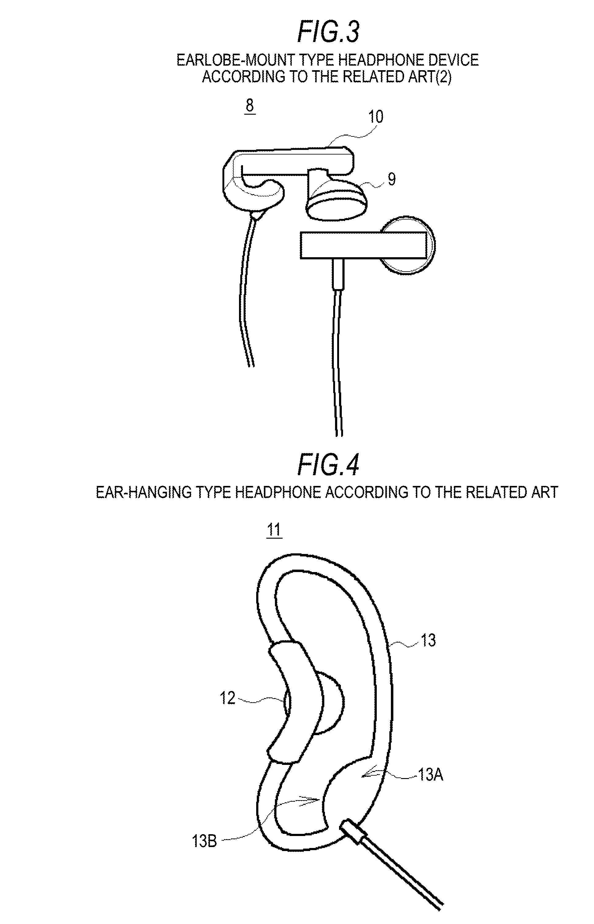
Further, the above-described earlobe-mounted headphone devices 5 and 8 (shown in FIGS. 2 and 3, respectively) have a problem in that it is painful for a user to wear the devices for a long time because a pressure is exerted on an earlobe of the user by the structure for sandwiching the earlobe of the user with the substantially U-shaped ear holding sections 7 and 10.

Method used


Image

  • Headphone device
  • Headphone device
  • Headphone device

Examples


first embodiment

1. First Embodiment

1-1. Configuration of Headphone Device

[0042]FIG. 5A is a front view of a headphone device 20 according to a first embodiment of the invention, and FIG. 5B is a side view of the headphone device 20.

[0043]The headphone device 20 includes an inner ear type driver unit 21, an earpiece 22 attached to an end of the driver unit, and an elongate sheet-like ear-holding section 23 which integrally holds the driver unit 21.

[0044]The driver unit 21 and a connection cable 24 are electrically connected in the ear-holding section 23, and the driver unit 21 outputs sounds according to electrical signals supplied from, for example, a portable audio player through the connection cable 24.

[0045]The part of the ear-holding section 23 to which the driver unit 21 is attached is in the form of an elongate thin plate, and the section includes an arm 23A which is curved so as to extend toward an end thereof substantially in the form of the character “U”. The ear-holding section 23 is form...

second embodiment

2. Second Embodiment

2-1. Configuration of Headphone Device

[0067]FIG. 9A is a front view of a headphone device 40 according to a second embodiment of the invention, parts identical between FIGS. 9A and 5B being indicated using like reference numerals. FIG. 9B is a view of the headphone device 40 taken when the device is mounted to an ear of a user, parts identical between FIGS. 9B and 7B being indicated using like reference numerals.

[0068]The headphone device 40 includes an inner ear type driver unit 21, an earpiece 22 attached to an end of the driver unit, and a substantially U-shaped cylindrical ear-holding section 43 which integrally holds the driver unit 21.

[0069]The driver unit 21 and a connection cable 24 are electrically connected in the ear-holding section 43, and the driver unit 21 outputs sounds according to electrical signals supplied from, for example, a portable audio player through the connection cable 24.

[0070]The ear-holding section 43 includes an arm 43A which is cur...

third embodiment

3. Third Embodiment

3-1. Configuration of Headphone Device

[0090]FIG. 10A is a side view of a headphone device 50 according to a third embodiment of the invention, parts identical between FIGS. 10A and 5B being indicated using like reference numerals.

[0091]FIG. 10B is a view of the headphone device 50 taken when the device is mounted to an ear of a user, parts identical between

[0092]FIGS. 10B and 7B being indicated using like reference numerals. The headphone device 50 includes an inner ear type driver unit 21, an earpiece 22 attached to an end of the driver unit, and a substantially U-shaped cylindrical ear-holding section 53 which integrally holds the driver unit 21.

[0093]The driver unit 21 and a connection cable 24 are electrically connected in the ear-holding section 53, and the driver unit 21 outputs sounds according to electrical signals supplied from, for example, a portable audio player through the connection cable 24.

[0094]The ear-holding section 53 includes an arm 53A which ...


PUM


Abstract

A headphone device includes: a driver unit held in the vicinity of the external acoustic meatus of an ear; and an arm in a predetermined shape formed integrally with the driver unit and extending from the driver unit, wherein an end of the arm is kept abutting on a part of the auricle near the base the auricle on a back side thereof to support the device at two support points provided by the driver unit and the end of the arm.

Description

BACKGROUND OF THE INVENTION[0001]1. Field of the Invention[0002]The present invention relates to a headphone device and, more particularly, the invention can be advantageously applied to a compact and lightweight headphone device which is used by connecting it to, for example, a portable audio player.[0003]2. Description of the Related Art[0004]As shown in FIG. 1, a so-called clip type headphone device 1 according to the related art includes a main body 2 incorporating a driver unit and a hanging type earpiece 3, and the device is held on an auricle of a user by sandwiching an upper part of the auricle with an upper part 3A of the hanging type earpiece 3.[0005]As shown in FIG. 2, a so-called earlobe-mounded headphone device 5 includes a driver unit 6 and a substantially U-shaped ear-holding section 7 attached to the driver unit 6, and the device is held on a ear of a user by sandwiching the earlobe with the ear-holding section 7.[0006]Further, as shown in FIG. 3, another earlobe-mou...

Claims


Application Information

Patent Timeline
Patent Type & Authority Applications(United States)
IPC IPC(8): H04R1/02
CPCH04R1/105
Inventor MUROZAKI, KATSUNORI
Owner SONY CORP
Why Eureka
Try Eureka