Direct-current discharge lamp

a discharge lamp and direct current technology, applied in the direction of electric discharge lamps, gas-filled discharge tubes, solid cathodes, etc., can solve the problems of correspondingly long service life, and achieve the effect of reliable reduction of material evaporation

Active Publication Date: 2012-02-21
OSRAM GMBH
View PDF3 Cites 0 Cited by
  • Summary
  • Abstract
  • Description
  • Claims
  • Application Information

AI Technical Summary

Benefits of technology

[0005]It is therefore one object of the present invention to provide a direct current discharge lamp of the type mentioned at the beginning that has a reduced blackening of the discharge vessel and thus a lengthened service life.
[0006]According to one embodiment of the invention, a direct current discharge lamp that has a reduced blackening of the discharge vessel and therefore a lengthened service life is characterized in that at least the distance between the anode and the cathode, the electric power and a geometry of the anode are adapted to one another in such a way that a region of a surface of the anode facing the cathode is free flowing in the heated state of the direct current discharge lamp. In other words, by adapting at least said parameters a free flowing state of the material of the anode is specifically produced during operation of the direct current discharge lamp in the region of its surface facing the cathode such that deformations of the surface occurring during operation are automatically compensated by subsequent flowing of the material, and a uniform anode plateau is ensured. This reliably prevents the occurrence of local growths with the associated high temperatures, and so there is a substantial reduction in the evaporation of the anode material. Owing to the self-healing ability of the anode, the direct current discharge lamp there fore exhibits a substantially weaker blackening of the discharge vessel and has a correspondingly lengthened service life.
[0009]It has further proved to be advantageous in this case that the anode is of rotationally symmetrical design at least along a longitudinal region facing the cathode. During the heated state of the direct current discharge lamp, this permits on the surface of the anode the formation of a “melt pool” of large area and permanent stability. Because of the fact that the arc is attached over a large area and uniformly, the occurrence of operating temperatures above the respective evaporation temperature of the anode material is reliably avoided.
[0010]In a further advantageous refinement of the invention, it is provided that starting from the surface facing the cathode, the anode has a length of at least 5 mm. In this way, the anode acts in the heated state as a thermal heat store, thus ensuring that the temperature of the surface facing the cathode is as uniform as possible.
[0018]A denoting the volume of the anode in mm3 on the first 5 mm length starting from the surface facing the cathode. This ensures an operation of the direct current discharge lamp in a region in which, given gas discharge lamps with anodes of sufficient length, on the one hand the required ability to free flow, and on the other hand a reliable reduction in the evaporation of the material of the anode in the region of the surface are attained.

Problems solved by technology

Owing to the self-healing ability of the anode, the direct current discharge lamp there fore exhibits a substantially weaker blackening of the discharge vessel and has a correspondingly lengthened service life.
Such a limitation of the fluidity ensures that during operation of the direct current discharge lamp the material of the anode has a sufficiently high viscosity, and also that there is no macroscopic deformation owing to increased or frequent effects of force.

Method used


Image

  • Direct-current discharge lamp
  • Direct-current discharge lamp

Examples


Embodiment Construction

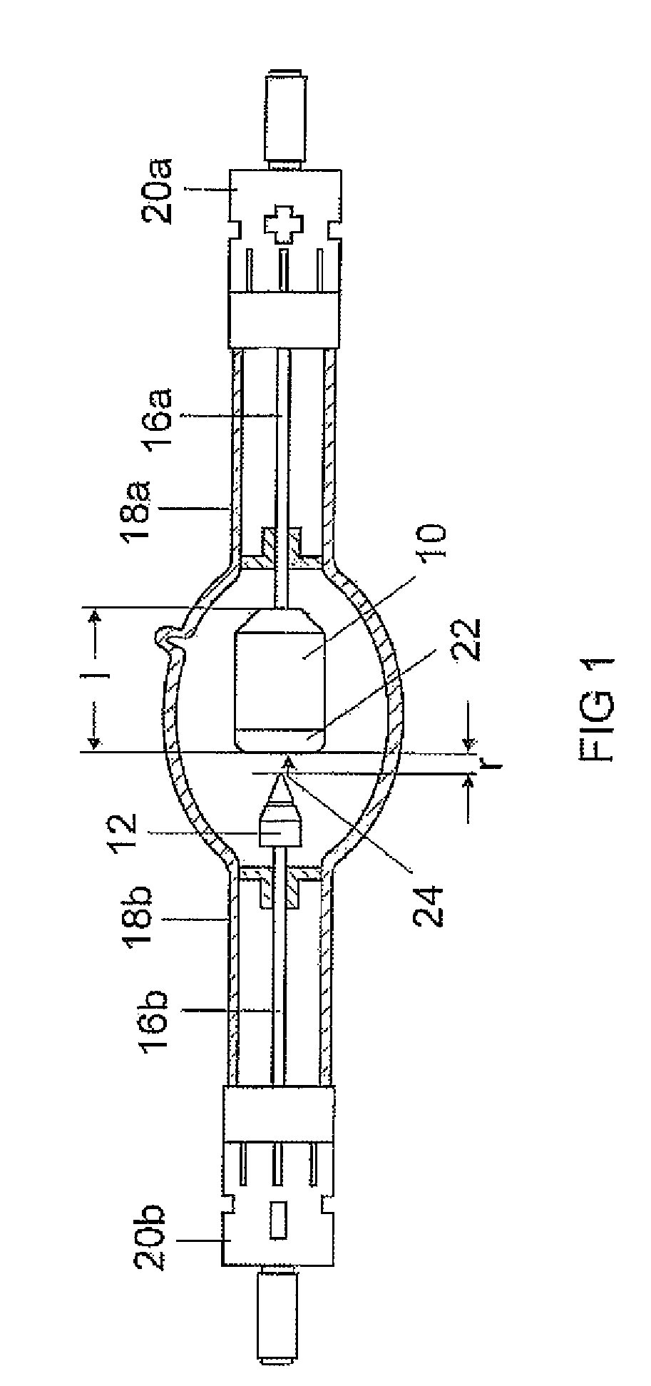
[0021]FIG. 1 shows a schematic and partially sectioned side view of a direct current discharge lamp in accordance with an exemplary embodiment, in this case designed as a xenon short arc lamp. The direct current discharge lamp in this case comprises an anode 10 and a cathode 12 that are arranged opposite one another at a predetermined distance r inside a discharge vessel 14 filled with xenon. The anode 10 in this case has a length 1 that can, for example, be selected between 15 mm and 50 mm as a function of the watt number of the direct current discharge lamp. The anode 10 and the cathode 12 are, furthermore, coupled to corresponding base elements 20a, 20b via assigned connecting elements 16a, 16b that are guided through shaft tubes 18a, 18b of the direct current discharge lamp which are sealed in a gastight fashion. An electric power P can be applied via the base elements 20a, 20b to the anode 10 and the cathode 12 in order to produce a gas discharge or to form an arc. Both the ano...


PUM


Abstract

A direct current discharge lamp with an anode (10) and a cathode (12) that are arranged opposite one another at a predetermined distance (r) inside a discharge vessel (14) filled with a filling gas, it being possible to apply electric power (P) to the anode (10) and the cathode (12) in order to produce a gas discharge. At least the predetermined distance (r) between the anode (10) and the cathode (12), the electric power (P) and a geometry of the anode (10) are adapted to one another in such a way that a region (22) of a surface (24) of the anode (10) facing the cathode (12) is free flowing in the heated state of the direct current discharge lamp.

Description

RELATED APPLICATIONS[0001]This is a U.S. national stage of application No. PCT / EP2007 / 060042, filed on Sep. 21, 2007.FIELD OF THE INVENTION[0002]The invention relates to a direct current discharge lamp with an anode and a cathode that are arranged opposite one another at a predetermined distance inside a discharge vessel filled with a filling gas, it being possible to apply electric power to the anode and the cathode in order to produce a gas discharge.BACKGROUND OF THE INVENTION[0003]Such a direct current discharge lamp may already be taken as known from the prior art and comprises an anode and a cathode that are arranged opposite one another at a predetermined distance inside a discharge vessel (14) filled with a filling gas. In order to produce light, an electric power can be applied to the anode and the cathode, the result being the formation of a gas discharge in the region of an arc.[0004]A disadvantageous circumstance with the known direct current discharge lamps may be seen ...

Claims


Application Information

Patent Timeline
Patent Type & Authority Patents(United States)
IPC IPC(8): H01J17/04
CPCH01J61/073H01J61/86H01J61/82
Inventor BAACKE, SWEN-UWEBERNDANNER, STEPHANLOFFLER, GERHARDROSENTHAL, DIRK
Owner OSRAM GMBH
Why Eureka
Try Eureka