Method and apparatus for warming-up and starting up luminous tube

A starting device and lamp technology, applied in lighting devices, light sources, electrical components, etc., can solve the problems of different starting time and unclear preheating time, and achieve the effects of simplified components, accurate preheating and starting time

Active Publication Date: 2007-05-09
IND TECH RES INST
View PDF0 Cites 0 Cited by
  • Summary
  • Abstract
  • Description
  • Claims
  • Application Information

AI Technical Summary

Problems solved by technology

[0006] Although the above method can preheat the lamp tube in advance to avoid the blackening of the lamp tube, but the grasp of the preheating time is not clear, and the aging of the electronic parts will The startup time is different each time

Method used


Image

  • Method and apparatus for warming-up and starting up luminous tube
  • Method and apparatus for warming-up and starting up luminous tube
  • Method and apparatus for warming-up and starting up luminous tube

Examples


Embodiment Construction

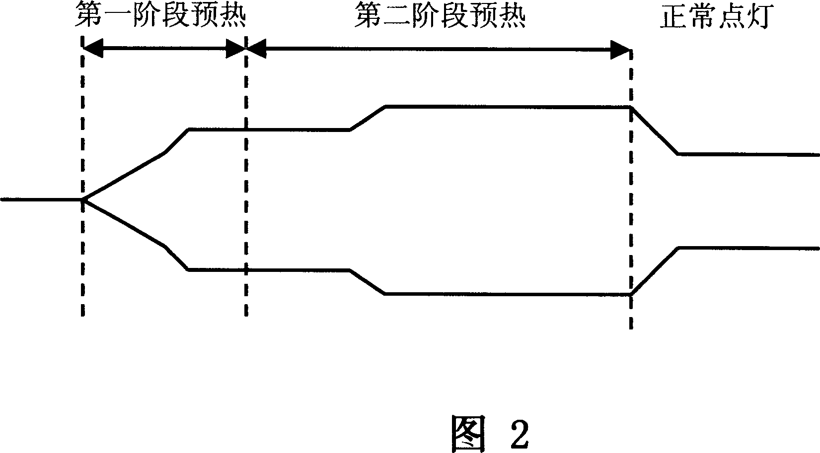
[0067] The present invention is an electronic ballast for lighting a lamp tube. The lamp filament is preheated by a frequency conversion preheating mode and then the lamp tube is started. As shown in FIG. 2, it is a waveform diagram of the filament preheating disclosed in the present invention. , The lamp is turned on after the first preheating time and the second preheating time in the frequency conversion preheating method, so the preheating time can be accurately grasped, and the start time of each time will not be different due to the aging of the electronic parts. The preheating method disclosed in the present invention realizes frequency conversion by means of electronic circuits and software, adopts flexible starting of the lamp tube, can achieve the purpose of using on lamp tubes of different starting forms and effectively extending the life of the lamp tube.

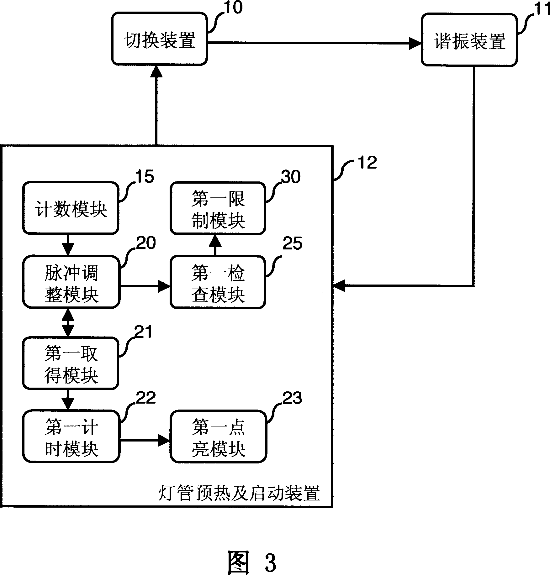
[0068] Please refer to FIG. 3, which is a block diagram of the first lamp preheating and starting device 12 discl...


PUM


Abstract

The apparatus thereof outputs a pulse in a preset frequency to drive at least one switch device and to let the luminous tube end of resonance device connected to the switch device to generate a trigger voltage by which pre-heating and lighting the luminous tube. The invention can shorten the pre-heat time using software solution, simplify the electronic circuit and adopt different pre-heating time for filament according to the luminous tube trigger type so as to extending the service life of luminous tube.

Description

Technical field [0001] The invention relates to a lamp tube preheating and starting method and a device thereof, in particular to a lamp tube preheating that uses a frequency conversion method to preheat the filament to reduce the phenomenon of lamp tube blackening and prolong the service life of the lamp tube And starting method and device. Background technique [0002] Please refer to Figure 1, which is a basic circuit structure diagram of a well-known electronic ballast. The electronic ballast is composed of various electronic components. For example, the power input module 1 is composed of electromagnetic interference (EMI) filters to eliminate the passage of AC lines. The noise is converted from AC to DC through the full-wave rectifier module 2 and output to the conversion module 3. The conversion module 3 converts the DC line voltage from the power input module 1 into a high frequency and high voltage current to drive the lamp tube. The control module 4 protects the circuit...

Claims


Application Information

Patent Timeline
Patent Type & Authority Applications(China)
IPC IPC(8): H05B41/14H05B41/295
Inventor 钟辉雄李丽玲古忠平陈燧宗
Owner IND TECH RES INST
Why Eureka
Try Eureka