Radio frequency environment object monitoring system and methods of use

a technology of environment object and radio frequency, applied in the direction of using reradiation, burglar alarm mechanical actuation, instruments, etc., can solve the problems of not being able to determine whether a particular door is open or closed, and being unable to economically tag individual items such as nails, bolts, batteries,

Active Publication Date: 2012-02-21
RF CONTROLS
View PDF47 Cites 237 Cited by
  • Summary
  • Abstract
  • Description
  • Claims
  • Application Information

AI Technical Summary

Benefits of technology

[0049]As disclosed in PCT / US08 / 58824, the ITCS is able to detect so called pseudo emitters and use multi-path ambiguity resolution algorithms to reduce or eliminate positional ambiguity these signals introduce when attempting to identify the locations of RFID tagged items in a target area. While the prior ITCS RFID tracking and location systems included extensive logic dedicated to the identification and rejection of these pseudo emitter signals, the present invention recognizes that these signals, especially when their appearance, location and / or disappearance is tracked over time as part of the overall RF environment fingerprint present in a target area, may be interpreted as an object presence and / or location indicator for untagged objects within the target area.
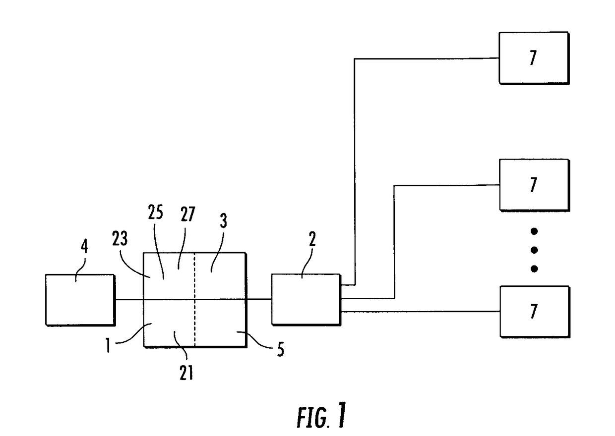
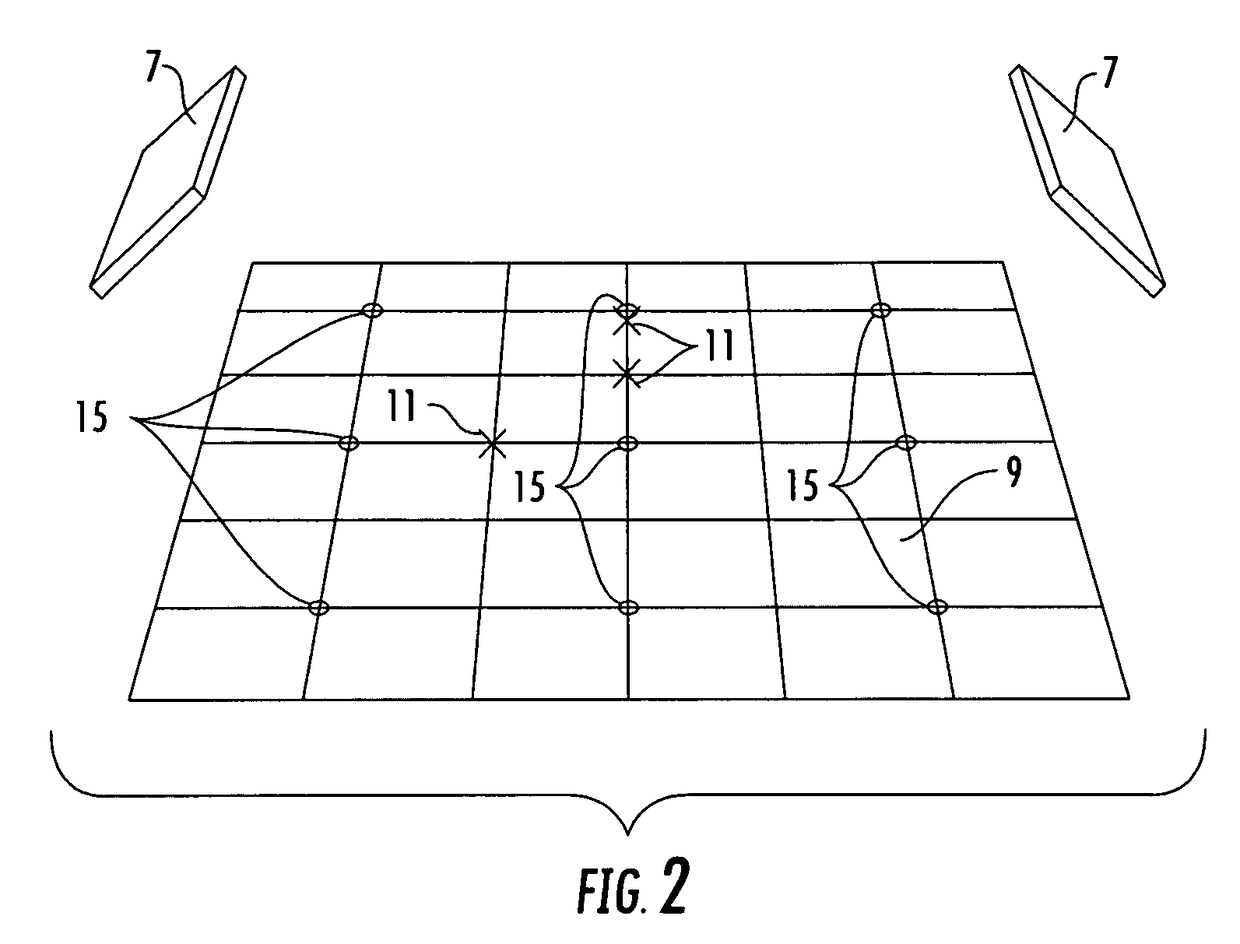
[0051]The rules engine 5 compares the real time RF environment fingerprint with a set of baseline calibration RF environment fingerprint data sets to identify pseudo emitter and / or response signal degradation indications of changes to the number and / or position of untagged objects present in the target area. Resolution of the location, pseudo emitter and / or response signal degradation indications is greatly increased when multiple antenna(s) 7 of the ITCS are arrayed about the target area 9, for example as shown in FIG. 2. At least two antenna(s) 7 enabling the application of triangulation logic between a beam vector of each antenna 7 to generate an accurate z-axis position parameter of signal sources useful alone or as a further accuracy check upon z-axis estimates derived from signal timing routines.
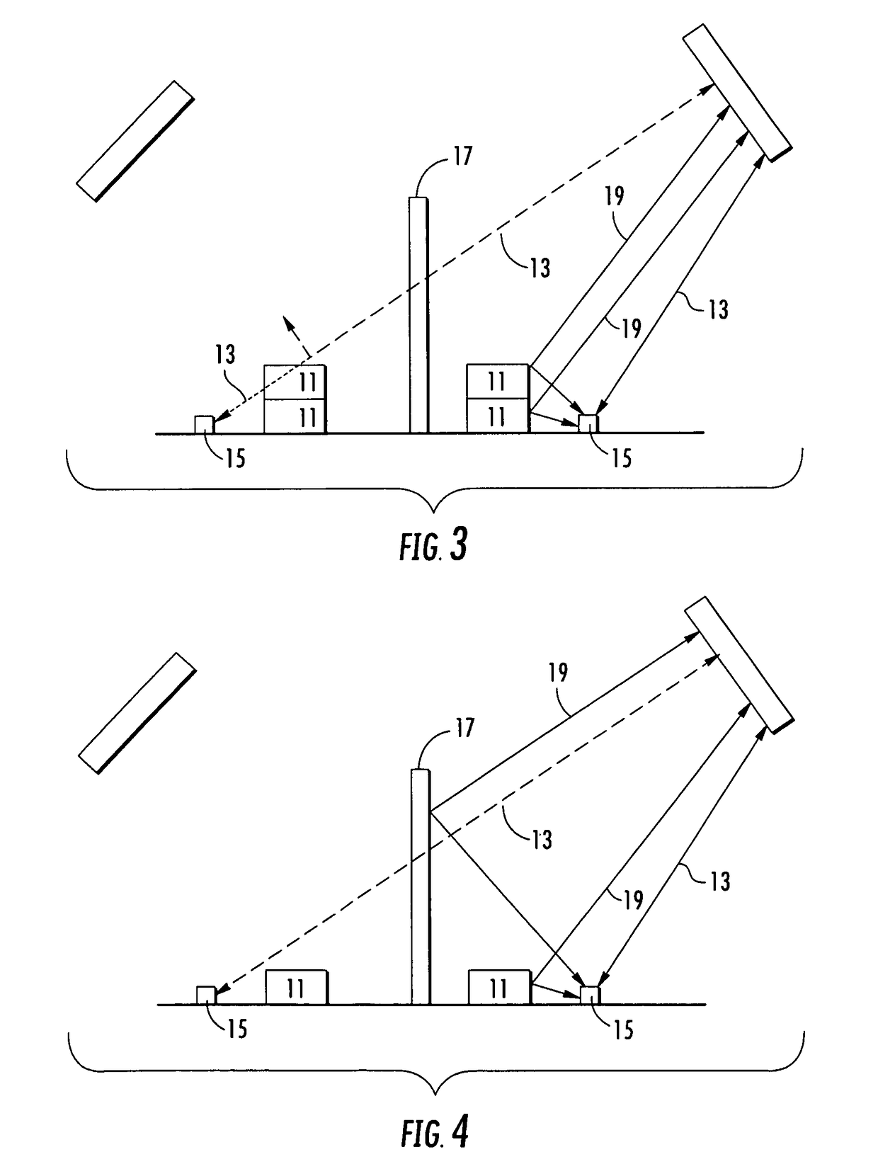
[0052]The rules engine 3 operates upon two primary indications of an untagged object(s) 11 presence in the target area 9, demonstrated in FIGS. 3-5. First, in a line of sight parameter 13, the response signal from a reference RFID tag 15, will become measurably degraded and / or cut off entirely as untagged object(s) 11 and / or structures 17 occur in and / or are placed in the signal path between the reference RFID tag 15 and an antenna 7, for example covering and / or obscuring the signal path to a reference RFID tag 15, thereby identifying the presence of an untagged object 11 along a signal path between the reference RFID tag 15 and an antenna 7. The reference RFID tag(s) 15 may be passive RFID tags permanently attached around the target area 9, for example on the floors, shelving and / or ceiling of a storeroom, warehouse or other space to be monitored. Second, in a pseudo emitter parameter 19, untagged objects and / or structures 17 including RF reflective surfaces (metal and / or metal coated surfaces) occurring and / or placed proximate a reference RFID tag 15 signal path will generate pseudo emitter responses with respect to that RFID tag 15 that may be located in three dimensions within the target area 9 as if they were RFID tags, themselves. Further, where separate antenna(s) 7 are arrayed about the target area 9, the different lines of sight between each antenna 7, various reference RFID tag(s) 15 and an untagged object 11 may generate both line of sight signal parameter 13 and pseudo emitter parameter 19 responses with respect to the same untagged object(s) 11, greatly improving the rules engine accuracy (for diagram clarity, representative signal paths / parameters are diagrammed with respect to only one of the antenna 7).
[0066]To improve signal quality, the background noise signature may be subtracted from any of the other signatures, such as the instantaneous signature, the average signature and the running reference signature, a procedure referred to as noise canceling.
[0074]The primary signature (sig prime) is then compared with the reference signature from the data matrix 5 in a further comparator processor 27. If there is a significant change, then the resulting nature of the change is routed to the rules engine 3, which triggers the appropriate action according to the established rules framework. If there is no significant change, then it is assumed that the environment has remained stable over the preceding period of time. The method using two antenna systems is the same. However because there are two steerable beam base stations, it is possible to more accurately determine a point in space using the azimuth and elevation positions from the two base stations to derive X, Y and Z positional information via triangulation. Further, dual (or more) signal beams intersecting at a desired location increase the interrogation signal intensity, for the desired point of interest, without radiating RF power beyond established limits, outside of the target area 9.
[0085]One skilled in the art will appreciate an advantage of the invention is that objects may be tracked and located without a need to individually tag them. By tagging the environment, for example the shelves and or object bins instead of each individual object, and recording how the RF environment fingerprint, including pseudo emitter parameter 19 signals associated with desired objects, then changes as the target area 9 is filled and / or emptied of objects, for example by comparison with a baseline data set, it is then possible to monitor the movement or change of position of untagged objects in the target area 9 with significant precision.

Problems solved by technology

Because of the nature of known RFID systems it is not always possible to determine whether particular tags are in a particular door.
Without special door sensors, it is not possible to determine whether a particular door is open or closed and whether an object is moving out of the distribution center or into the distribution center.
Further, many items have packaging that is not complementary to being tagged, such as metal cans and / or plastic bottles, such as soft drinks.
Also, it is not economical to tag individual items, such as nails, bolts, batteries, coins or the like.

Method used


Image

  • Radio frequency environment object monitoring system and methods of use
  • Radio frequency environment object monitoring system and methods of use
  • Radio frequency environment object monitoring system and methods of use

Examples


Embodiment Construction

[0029]The inventor has recognized that the entirety of the monitored radio frequency environment, hereafter referred to as the RF environment fingerprint, may be used to derive changes of object presence and / or location(s), even where the individual objects within the target area are not each provided with their own individual RFID tag.

[0030]It is possible to monitor the presence and / or direction of movement of an RFID tag within a three dimensional target area via RFID monitoring systems. For example, International Patent Application serial number PCT / US08 / 58824, titled “Radio Frequency Signal Acquisition and Source Location System” filed Mar. 30, 2008 by Bloy et al, and International Patent Application serial number PCT / IB2008 / 053643, titled “Steerable Phase Array Antenna RFID Tag Locater and Tracking System”, filed Sep. 9, 2008 by Bloy, both applications commonly owned with the present application and hereby incorporated by reference in their entirety, describe systems of coopera...


PUM


Abstract

A method and apparatus for monitoring untagged objects in a target area including calibrating a radio environment monitoring system including a rules engine and a baseline data set for a target area by recording a set of changes to the RF environment fingerprint of the target area received by the radio environment monitoring system as the target area is filled with objects. During system operation, scanning the target area with the radio environment monitoring system for a current RF environment fingerprint, comparing the current RF environment fingerprint with the baseline data set by a rules engine and reporting an output of the rules engine.

Description

BACKGROUND[0001]1. Field of the Invention[0002]This invention relates to a radio frequency environment monitoring system for object presence feedback. More particularly, the invention relates to a radio frequency environment monitoring system for RFID tagged and / or untagged object monitoring via analysis of changes to the monitored RF environment occurring as the objects present in the monitored area are varied in position and or number.[0003]2. Description of Related Art[0004]Previous RFID tag inventory and or object passage gateway monitoring systems have relied upon reading one or a plurality of tags, each tag representing a unit or known quantity of units of associated objects.[0005]It is not practical to apply an RFID tag to each object to be monitored, and / or it is desirable to monitor the presence of quantities of the objects to be monitored with greater precision than just a binary indication of an RFID tag associated with a quantity of objects each of which may or may not b...

Claims


Application Information

Patent Timeline
Patent Type & Authority Patents(United States)
IPC IPC(8): G08B13/14
CPCG01S13/003G01S13/04G01S13/758G06Q10/087G01S13/872G01S13/82G01S2013/0245
Inventor BLOY, GRAHAM P.
Owner RF CONTROLS
Why Eureka
Try Eureka