Cellular phone geolocation system

a geolocation system and cellular phone technology, applied in the field of cellular phone geolocation systems, can solve the problems of inability to accept location errors, loss of signal strength, and inability to locate users, so as to reduce or eliminate ambiguities, reduce or eliminate phase related ambiguities, and eliminate ambiguities

Inactive Publication Date: 2005-08-11
INFORMATION SYST LAB
View PDF19 Cites 10 Cited by
  • Summary
  • Abstract
  • Description
  • Claims
  • Application Information

AI Technical Summary

Benefits of technology

[0016] In each of the embodiments described above, the phase related ambiguities can be eliminated by a processor at the base station to find the real cellular phone position. It is to be appreciated that the number of ambiguities will depend on the wavelength(s) of the beacon signals, the size of the coverage area and the number and distribution of transmitters. Several techniques can be used to reduce or eliminate the ambiguities. A preferred technique involves using a high-resolution algorithm such as the Maximum Likelihood Method (MLM) to eliminate the phase related ambiguities and find the real receiver position.
[0017] Another technique for eliminating ambiguities involves using transmitters configured to transmit at multiple frequencies. Here, a set of possible receiver positions is produced for each frequency. The set of possible receiver positions produced at one frequency can then be compared to the set of possible receiver positions produced at a second frequency and any possible receiver positions that are not common to both sets can be eliminated as ambiguities. Once the ambiguities have been eliminated, the remaining position is the real position of the receiver relative to the transmitters. It is to be appreciated that a combination of the above-described techniques can be used to reduce or eliminate phase related ambiguities.

Problems solved by technology

Mobile cellular phones inherently present a more complex task of locating the user than traditional hard-wired phones.
This complexity is due to the fact that cellular phones continually change their physical location and are often powered off during some or all of this movement to preserve the charge on the phone's battery.
Lack of adequate signal penetration can result in a loss of signal strength which in turn can cause unacceptable location errors.
Unfortunately, radiofrequency (RF) systems using high frequency signals are limited in their ability to penetrate the walls and features of a structure.
This significant amplitude difference between direct and multipath signals will result in lower null depth and lower phase error due to the multipath signal.
Thus, the two signals will interfere causing deep nulls and significant phase error.
This phenomenon is the main reason that existing long-range low-frequency phase-only systems, such as Loran, do not work well in urban areas.
However, in time-of-arrival systems, increased resolution can only be obtained at the expense of increased bandwidth.
Unfortunately, this much bandwidth (tens of MHz) is unavailable at the low frequencies required to accurately locate objects within structures.

Method used


Image

  • Cellular phone geolocation system
  • Cellular phone geolocation system
  • Cellular phone geolocation system

Examples


Embodiment Construction

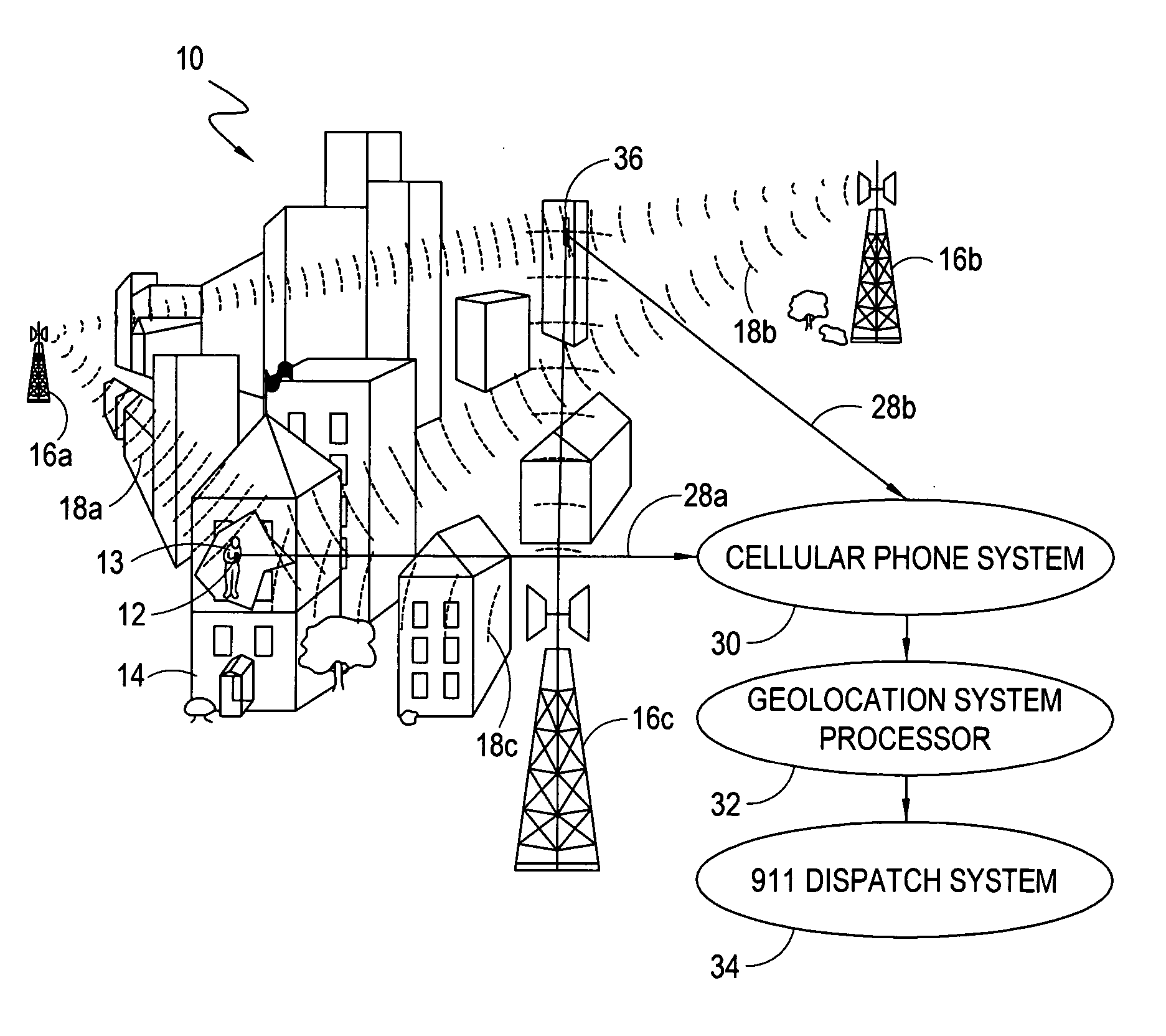
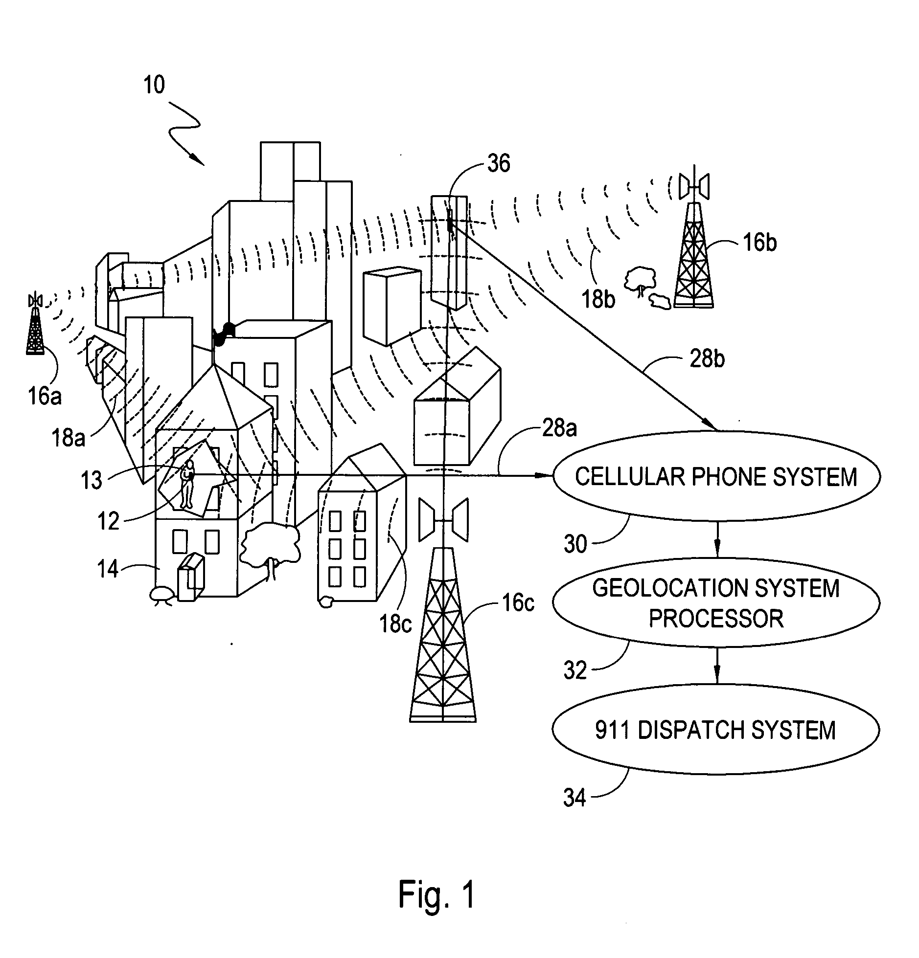
[0021] Referring initially to FIG. 1, an arrangement of a cellular phone geolocation system is shown and is generally designated 10. The basic object of the system 10 is to determine the location of a cellular phone 12, and if desired the user 13, within a cellular phone service area that can be an urban environment, as shown. Further, this is to be accomplished during periods when the cellular phone 12 is stationary or mobile, outdoors or inside a building such as exemplary building 14.

[0022] In overview, FIG. 1 shows that system 10 includes a plurality of transmitters 16a-c that can be installed on cell towers, as shown. In general, the transmitters 16a,b shown in FIG. 1 can be arbitrarily located as long as the transmitters 16a-c are mutually dispersed and their actual location is known. If possible, it is preferable to position the transmitters 16a-c relative to each other to obtain favorable geometric dilution of precision (GDOP). Although three transmitters 16a-c are shown in...


PUM


Abstract

A geolocation system for locating a cellular phone in a service area includes an auxiliary receive channel incorporated into the cellular phone. A plurality of transmitters are mutually dispersed at known locations to transmit low frequency beacon signals into the service area. Each beacon signal includes an identifying characteristic that can be used to identify the particular transmitter the signal emanated from. The low frequency of the signal prevents urban features within the service area from acting as signal waveguides and altering the path of the signal. When the user dials a predetermined number such as “911”, the auxiliary receive channel is activated to receive the transmission signals and extract phase related information and the identifying characteristic from each signal. The extracted information is then transmitted to a base station using the cellular phone's normal communication link where the information is processed to determine the location of the cellular phone.

Description

FIELD OF THE INVENTION [0001] The present invention pertains generally to cellular phone geolocation systems. More particularly, the present invention pertains to systems and methods for locating a cellular phone user within a cellular phone service area. The present invention is particularly, but not exclusively, useful as a system for locating a cellular phone user that has made an emergency 911 call. BACKGROUND OF THE INVENTION [0002] In many situations and for many reasons it may be desirable to locate the user of a cellular phone. Of particular interest is the desire to locate an emergency 911 caller within an urban area who may or may not be inside a building. Recently, the frequency of occurrences wherein it would be desirable to rapidly locate a cellular phone has increased dramatically. This is due in part because the number of cellular phone users is rapidly growing as wireless communication companies are continually finding ways to reach new consumers with the latest tech...

Claims


Application Information

Patent Timeline
Patent Type & Authority Applications(United States)
IPC IPC(8): G01S5/00G01S5/10H04W64/00
CPCG01S5/0036H04W64/00G01S5/10
Inventor HALSEY, J. DOSS
Owner INFORMATION SYST LAB
Why Eureka
Try Eureka