Fuel cell system with a metering unit

a fuel cell and metering unit technology, applied in the direction of fuel cells, electrochemical generators, electrical equipment, etc., can solve the problem of relative high cost, and achieve the effect of more cost-effective manufacture and operation of the fuel cell system

Active Publication Date: 2012-02-28
GM GLOBAL TECH OPERATIONS LLC +1
View PDF9 Cites 0 Cited by
  • Summary
  • Abstract
  • Description
  • Claims
  • Application Information

AI Technical Summary

Benefits of technology

[0009]The object of the present invention is to provide a fuel cell system with a fuel cell unit, in the case of which a metering unit with at least one metering valve is provided for metering a fuel for at least one anode of the fuel cell unit, and a start valve is provided for metering the fuel for at least one cathode of the fuel cell unit in a start phase, it being possible to manufacture and operate the fuel cell system more cost-effectively.
[0010]An inventive fuel cell system is therefore characterized by the fact that at least one fixed throttle element with an inner cross-sectional surface area is provided for establishing the maximum quantity of fuel that may be metered in the start phase, for the cathode in particular. With an inventive throttle element that includes these advantages, it become possible to limit the relatively small quantity of fuel required in the start phase, for the cathode in particular. This makes it possible to eliminate complex and expensive developments of special start valves. The costs to manufacture inventive fuel cell systems are reduced accordingly.
[0011]It also becomes possible, according to the present invention, to include start valves of the same type or with identical designs, e.g., in fuel cell systems with highly diverse outputs. The maximum quantity of fuel to be metered in the start phase for fuel cell units having different outputs is advantageously specified by the throttle element with the fixed inner cross-sectional area. Throttle elements with different inner cross-sectional areas or bores or the like are easy to manufacture. As a result, according to the present invention, the cost to develop and manufacture fuel cell systems with highly diverse outputs is also reduced.

Problems solved by technology

This results in relatively high costs, however.

Method used


Image

  • Fuel cell system with a metering unit
  • Fuel cell system with a metering unit
  • Fuel cell system with a metering unit

Examples


Embodiment Construction

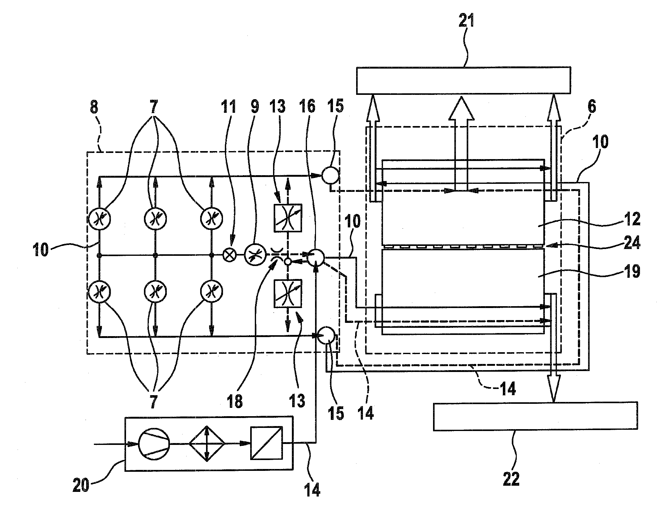
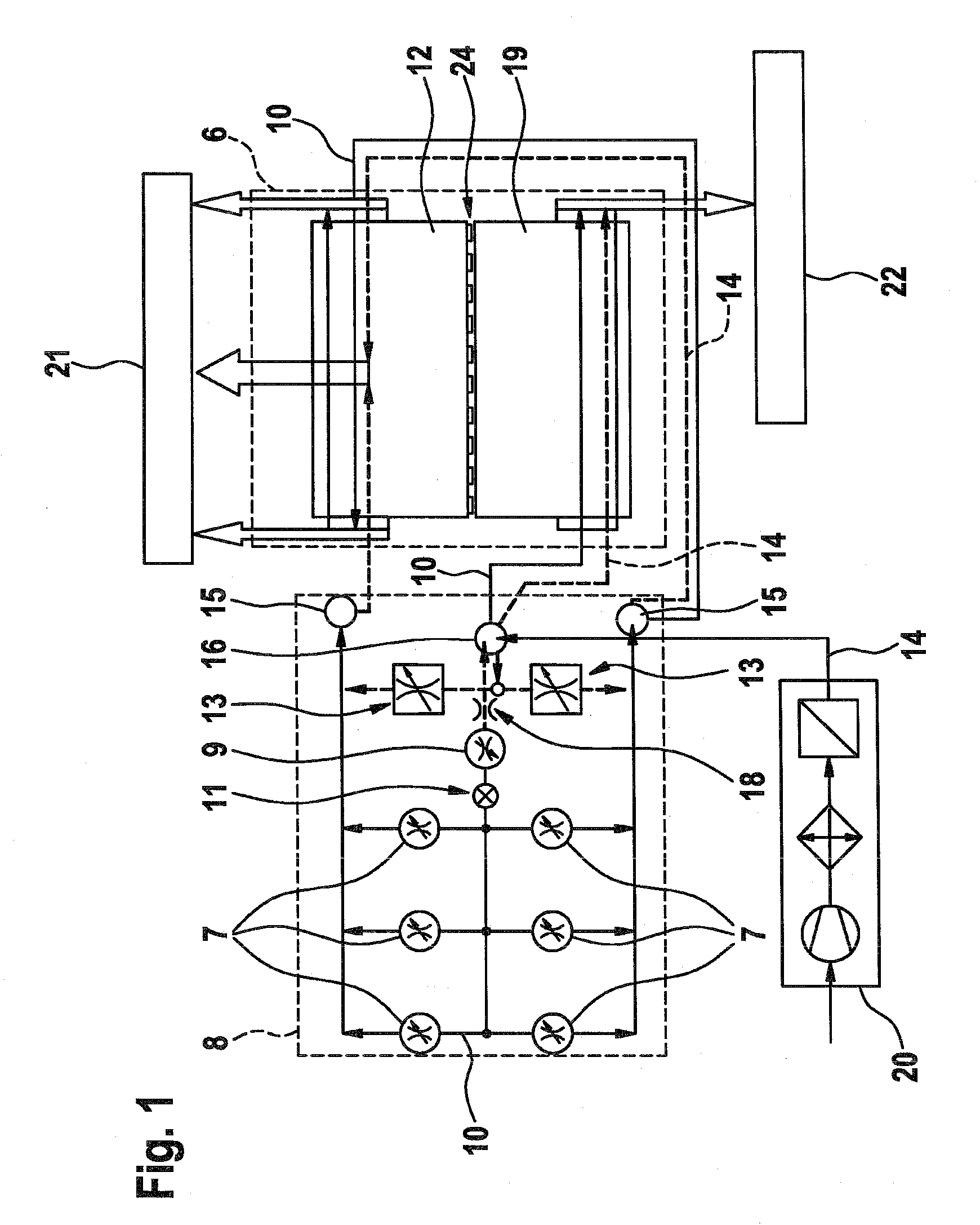
[0024]The block diagram of a fuel cell system according to the present invention, as shown in FIG. 1, includes a fuel cell unit 6, which is supplied with a fuel or hydrogen 10 for an anode 12, and with air 14 for a cathode 19 via a gas supply unit 8 or, in the exemplary embodiment shown, an “AIU” (anode inlet unit) 8.

[0025]An air supply unit 20 or a “CIU” (cathode inlet unit) 20 is installed upstream of AIU 8. It includes a pressure generator and / or a filter and / or a moisturizer, etc., as is common.

[0026]The system also includes an anode outlet unit (AOU) 21, with which its anode exhaust gasses are carried away. A cathode outlet unit (COU) 22 is also provided, with which the cathode exhaust gasses are carried away.

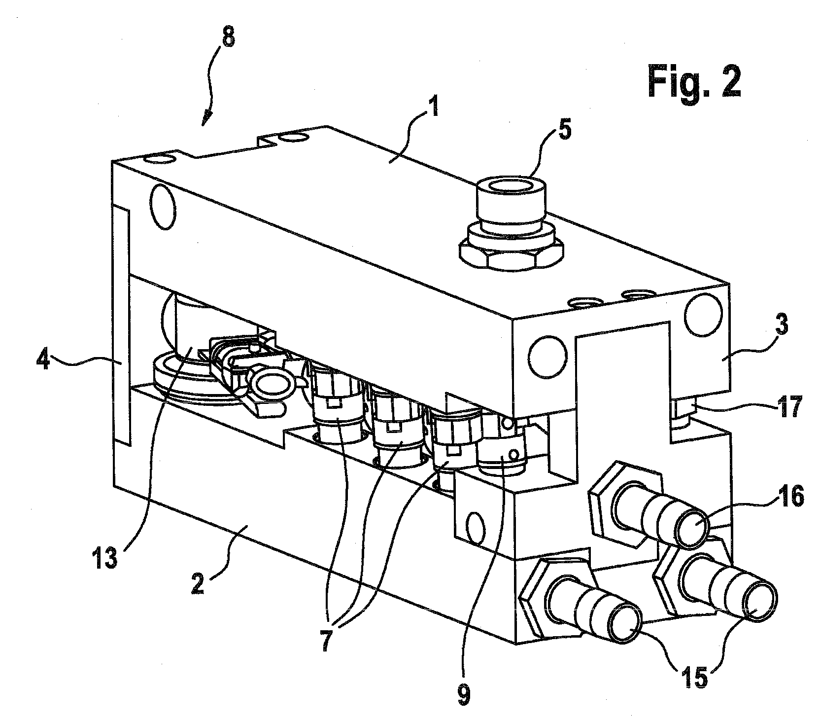
[0027]AIU 8 includes several metering valves 7. According to the variant shown, three valves connected in parallel are provided in each row. This makes it possible to realize a large metering-quantity range with a relatively high metering accuracy.

[0028]The two parallel-co...


PUM

PropertyMeasurementUnit
surface areaaaaaaaaaaa
pressureaaaaaaaaaa
proton-conductingaaaaaaaaaa

Abstract

The invention relates to a fuel cell installation comprising a fuel cell unit (6). Said installation is also provided with a dosing unit (8) which comprises at least one dosing valve (7) and is used to dose a fuel (10) for at least one anode (12) of the fuel cell unit (6), and a starting valve for dosing the fuel (10) for at least one cathode (19) of the fuel cell unit (6) during a starting phase. The aim of the invention is to be able to produce and operate one such fuel cell installation in an economical manner. To this end, at least one throttle element (18) comprising a fixed internal cross-sectional area is used to fix the maximum quantity of fuel that can be dosed in the starting phase.

Description

CROSS-REFERENCE TO RELATED APPLICATION[0001]The invention described and claimed hereinbelow is also described in German Patent Application DE 10 2005 055 741.4 filed on Nov. 23, 2005. This German Patent Application, whose subject matter is incorporated here by reference, provides the basis for a claim of priority of invention under 35 U.S.C. 119(a)-(d).BACKGROUND OF THE INVENTION[0002]The present invention relates to a fuel cell system with a fuel cell unit that includes a metering unit with at least one metering valve for metering the fuel, hydrogen in particular.[0003]Modern fuel cell systems for stationary and mobile applications are generally operated such that the anode side is supplied with fuel, hydrogen in particular, and the cathode side is supplied with oxygen, air in particular. The incoming and outgoing gas flows are pumped or blown and released through the fuel cell stack.[0004]At times, a relatively high portion of unconverted hydrogen is blown off of the anode side of...

Claims


Application Information

Patent Timeline
Patent Type & Authority Patents(United States)
IPC IPC(8): H01M8/04
CPCH01M8/04126H01M8/04231H01M8/04268Y02E60/50
Inventor NGUYEN-SCHAEFER, THANH-HUNGBRENNER, FRANKBANTLEON, GUENTHERSPARSCHUH, JENS-UWEHEBNER, THOMAS
Owner GM GLOBAL TECH OPERATIONS LLC
Why Eureka
Try Eureka