Method for operating a feces conveyor device

a technology for transporting devices and manure, which is applied in the field of manure transport devices and the operation of devices, can solve the problems of difficult to guide planar textile structures as conveyor belts, considerable difficulties in carrying away very moist, mushy mixtures, and the failure of swine breeding operations to use such an arrangement, and achieves the effect of very cost-effective operation and manufacturing

Inactive Publication Date: 2008-05-08
QALOVIS FARMER AUTOMATIC ENERGY
View PDF25 Cites 4 Cited by
  • Summary
  • Abstract
  • Description
  • Claims
  • Application Information

AI Technical Summary

Benefits of technology

[0013] The invention provides a manure conveying device for livestock breeding operations in which a separation of manure and urine occurs, in which the straight course of the belt is guaranteed despite substantial fouling. According to aspects of the invention, a cleaning of the return rollers takes place. The device may be manufactured and operated very cost-effectively.
[0022] In implementations, the return rollers are made of stainless steel, so that it is possible to add acids to the urine in order to avoid ammonia losses. The trough in which the lower belt half runs is preferably formed by a corresponding plastic sheet, which has the characteristics of being absolutely leak-proof and having a high sliding ability. In this manner, the lower belt half, and thus the belt, can slide on this sheet without difficulty.
[0026] Implementations of the invention provide a manure transport device that ensures a separation of urine and solid manure, whereby the manure is transferred to the manure collection channel well dried. At the same time, a continuous conveyance of the manure and urine occurs, which ensures that a good stall climate (i.e., a high air quality) is achieved. Moreover, despite considerable fouling, the belt is always kept on a straight course and a continuous cleaning of the return rollers takes place. Since at least one return roller is tensioned, the plastic belt can always be kept sufficiently tensioned, irrespective of the temperatures and loads prevailing in the stall.

Problems solved by technology

However, with the device according to DE 195 14 574 C1, the problem arises that it is difficult to guide planar textile structures as conveyor belts because they always have the tendency to slip from the drive and return rollers due to the fact that the textile structure does not allow a trouble-free guiding of the belt.
With livestock breeding operations in which animals are kept that excrete solid manure and liquid urine (e.g., pigs), considerable difficulties arise in carrying away this very moist, mushy mixture.
The use of such an arrangement in the case of swine breeding operations would not be successful, since the solid manure involved is still relatively soft and would fall through the fall-through grating.
If conveyor belts are used in swine breeding operations for the removal of the manure, a very quick fouling of the return rollers occurs so that the conveyor belts slip off laterally.
Likewise, attempts in practice to embody the drive roller and / or the return roller in a convex manner in order to achieve a straight course of the conveyor belt have not been successful because the fouling is too great and the solid manure components equalize the convexity of the return roller and drive roller.
Moreover, attempts to design the return roller and / or drive roller as latticed rollers in order to achieve an appropriate guidance have not been successful either, since these rollers become clogged inside the lattice extremely quickly.
This known device has proven itself in practice, but is very expensive in constructional terms.

Method used


Image

  • Method for operating a feces conveyor device
  • Method for operating a feces conveyor device
  • Method for operating a feces conveyor device

Examples


Embodiment Construction

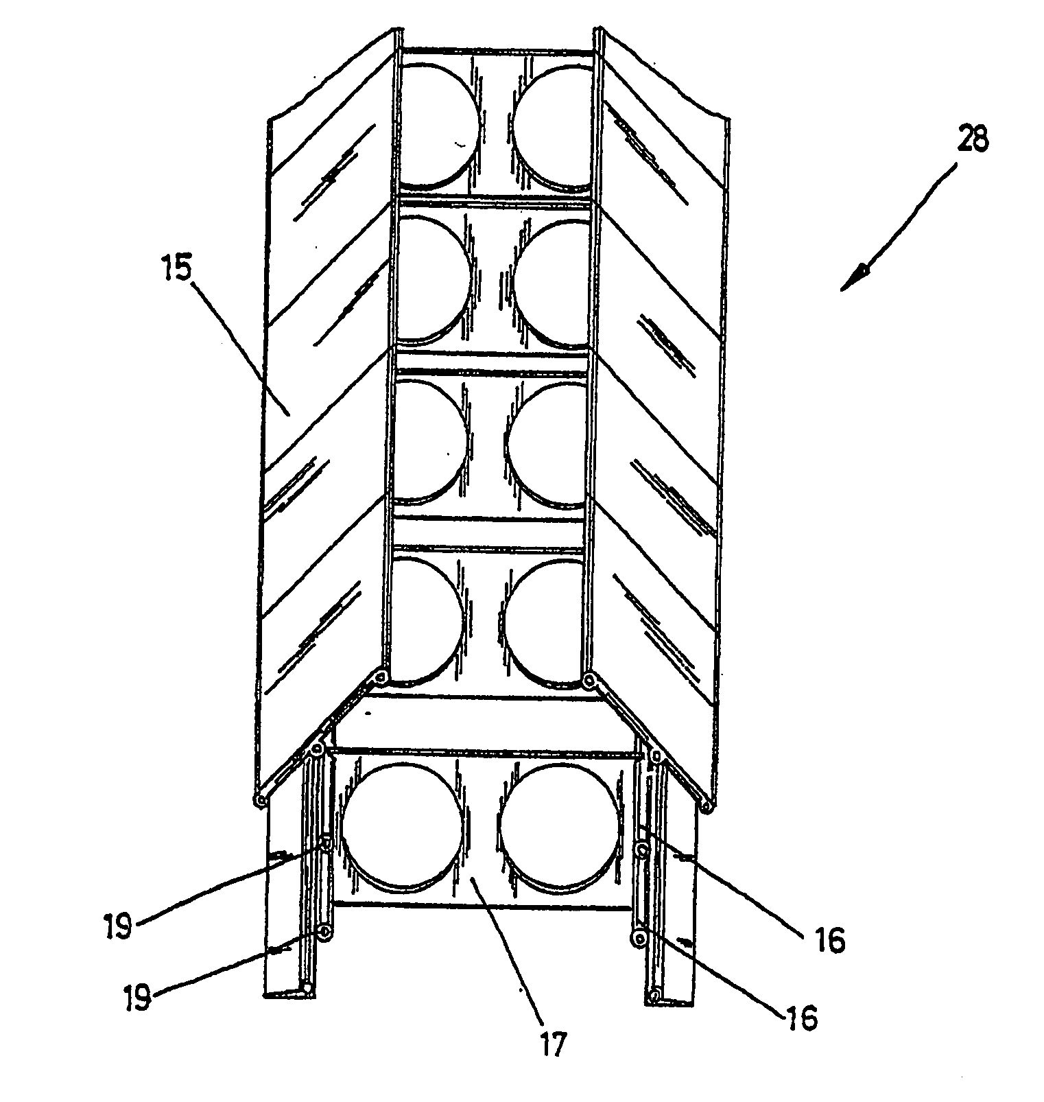
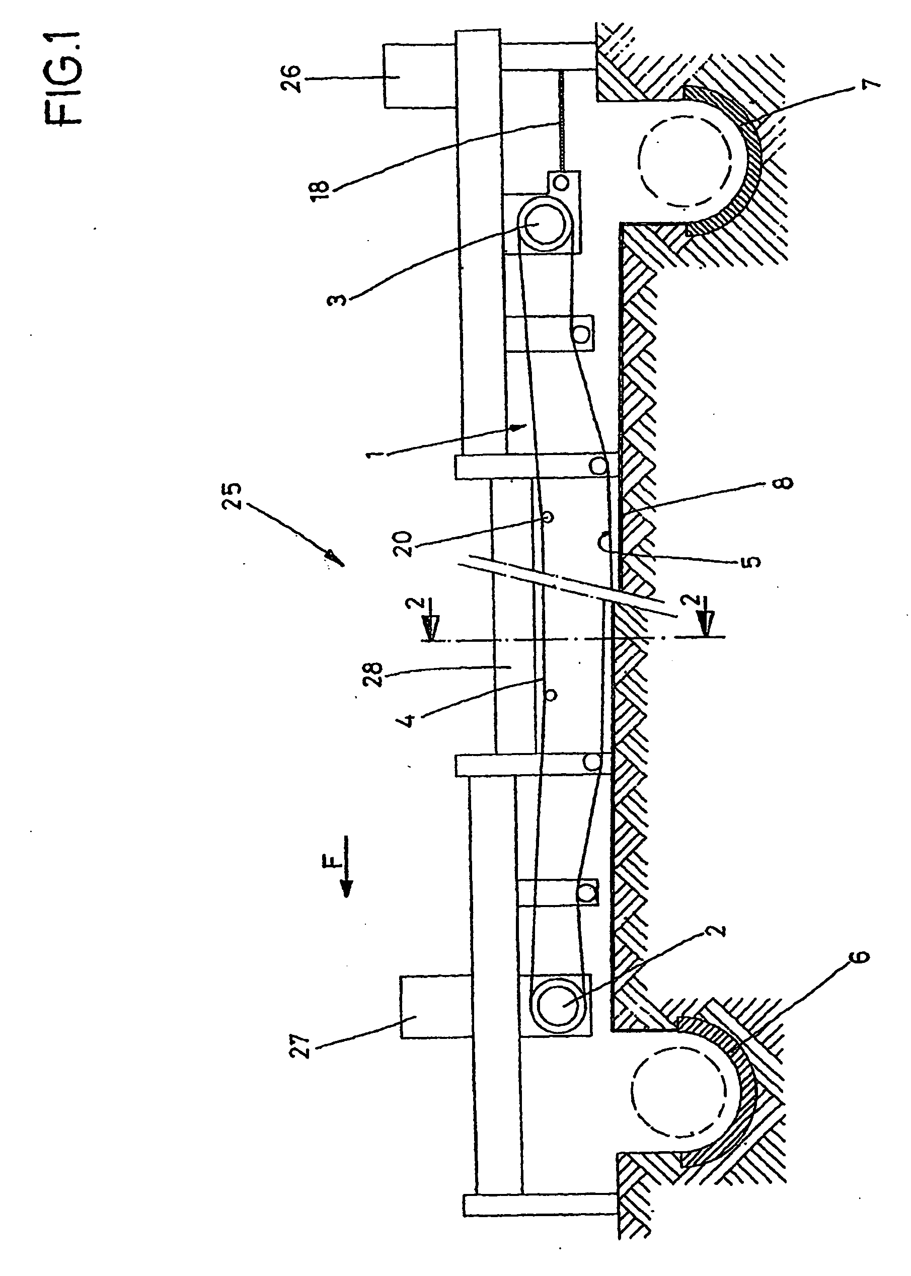
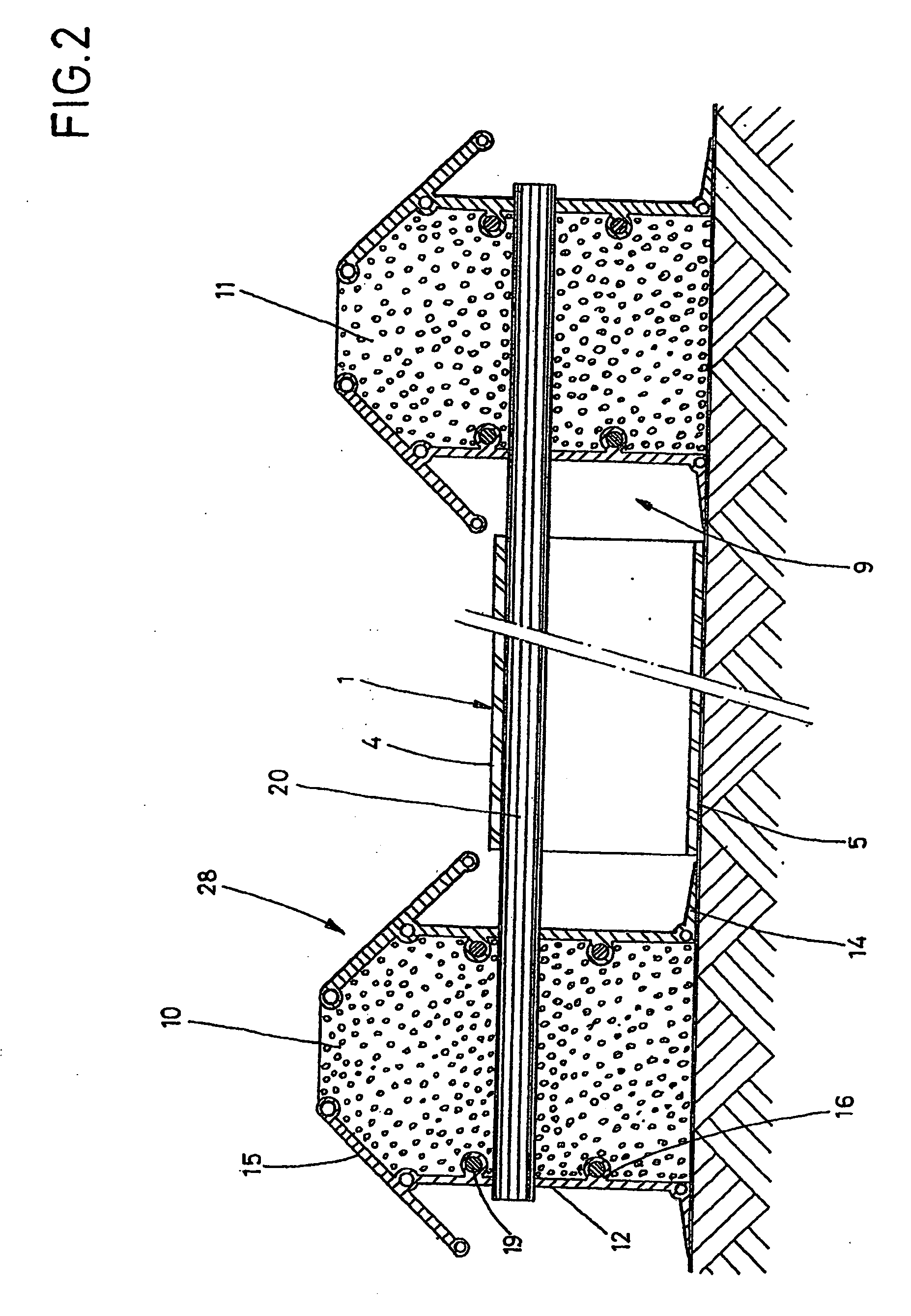
[0042]FIG. 1 shows a manure transport device 25 that features a manure conveyor belt 1 which comprises, e.g., a perforated plastic belt that is guided around return rollers 2 and 3 so that an upper belt half 4 and a lower belt half 5 are formed. The belt may be used for livestock operations, such as, for example, underneath a manure-permeable stall floor. The upper belt half 4 rests on bearing shafts 20 and the lower belt half 5 rests on a plastic sheet (not shown for clarity) lying on the base 8, so that a good sliding ability of the plastic belt on the plastic sheet of the base is ensured. The return roller 3 is supported in an adjustable manner so that it can be tensioned via a tensioning device 18. It is thus possible to keep the plastic belt 1 always equally tensioned constantly irrespective of prevailing temperature conditions. The tensioning device 18 can work mechanically, hydraulically or pneumatically and can be controlled automatically or individually.

[0043] Electric mot...


PUM


Abstract

A system and method for operating a manure conveyor device. The method includes driving a first return roller about which a manure conveyor belt circulates at a first rotational speed, and driving a second return roller about which the manure conveyor belt circulates at a second rotational speed. During a first interval the first rotational speed exceeds the second rotational speed, and during a second interval the second rotational speed exceeds the first rotational speed.

Description

CROSS REFERENCE TO RELATED APPLICATIONS [0001] This application is a divisional application of U.S. application Ser. No. 10 / 562,645, which is a National Stage of International Application No. PCT / DE2005 / 000994, filed on Jun. 2, 2005, and claims priority to German Patent Application No. 10 2005 007 120.1, which was filed on Feb. 17, 2005. The disclosure of U.S. application Ser. No. 10 / 562,645 is expressly incorporated by reference herein in its entirety.BACKGROUND OF THE INVENTION [0002] 1. Field of the Invention [0003] The invention relates to a method and a device for operating a manure transport device for livestock breeding operations. [0004] 2. Discussion of Background Information [0005] Manure transport devices for livestock breeding operations comprising a manure conveyor belt driven in a circulating manner arranged underneath a stall floor and having a return roller are known, for example, from German Pat. No. DE 195 14 574 C1. This known device is suitable for poultry breedi...

Claims


Application Information

Patent Timeline
Patent Type & Authority Applications(United States)
IPC IPC(8): A01K1/01
CPCA01K1/0135A01K1/0103
Inventor KUEHLMANN, JOSEF
Owner QALOVIS FARMER AUTOMATIC ENERGY
Why Eureka
Try Eureka