
Electromagnetic vibrator and producing method thereof

a technology of electromagnetic vibrator and vibrator plate, which is applied in the direction of electrical transducer, dynamo-electric machines, transducer details, etc., can solve the problems of large size of vibrator, low efficiency, and insufficient conversion of electrical energy into mechanical energy, so as to improve structure and production process, stable natural frequency, and high efficiency

Active Publication Date: 2012-03-06
NINGBO SHENGYA ELECTRONICS
View PDF22 Cites 4 Cited by
  • Summary
  • Abstract
  • Description
  • Claims
  • Application Information

AI Technical Summary

Benefits of technology

[0006]The main object of the present invention is to provide an electromagnetic vibrator to overcome the disadvantage of current using technology. Based on the vibration principle and construct of speakers, the present invention improves the structure and production process, to achieve a stable natural frequency and a high efficiency, as well as a simplified structure and high stability.
[0007]The present invention also provides a process of manufacture of an electromagnetic vibrator, which is easy to perform, the product passing rate and consistency is high.

Problems solved by technology

But this type of vibrator has a large size, the vibration frequency is low, the frequency range is small, the efficiency is low and can not sufficiently transform the electrical energy into mechanical energy.
The usage of this type of vibrator is limited, especially when high frequency is required.
In the point of chemistry, generally the glue is using van der Waals force or Hydrogen bond instead of chemical bond, so the reliability is always a problem.
The process is complex, difficult to maintain the consistency and stability, so as to the quality of the product.
The application of the product is limited.

Method used


Image

  • Electromagnetic vibrator and producing method thereof
  • Electromagnetic vibrator and producing method thereof
  • Electromagnetic vibrator and producing method thereof

Examples


Embodiment Construction

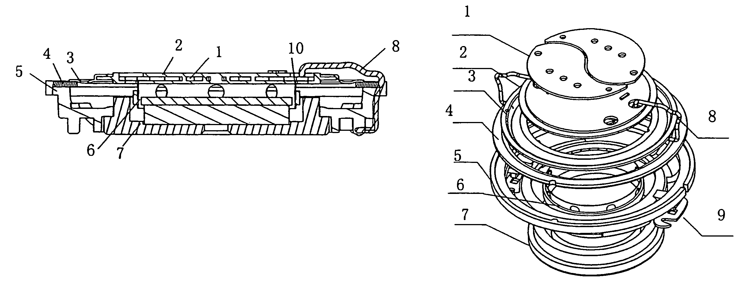
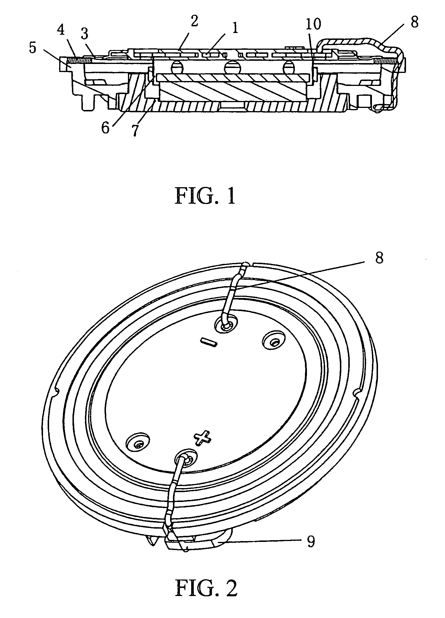
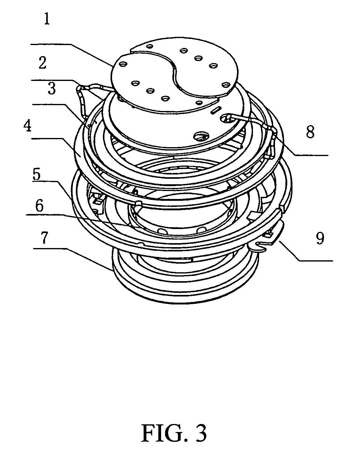
[0031]Referring to FIGS. 1, 3 and 4, an electromagnetic vibrator according to a preferred embodiment of the present invention is illustrated, wherein the electromagnetic vibrator comprises a vibration sheet 2, a suspension edge 3, a basin frame 5, and a magnetic loop system 7. The vibration sheet 2 comprises two conductive sheets 1 sealed therewithin, wherein the two conductive sheets 1 are spaced apart from each other and are aligned to form a round shape. The vibration sheet 2 is connected with the suspension edge 3 first, and then connected with a gasket 4, and then connected with the whole basin frame 5. The lower edge of the suspension edge 3 is connected with a voice coil 6. The other end of the voice coil 6 is suspended over the permanent magnet of the magnetic loop system 7, wherein the permanent magnet of the magnetic loop system 7 is formed as a one piece magnetic vibration provider for providing a magnetic field. The magnetic loop system 7 is affixed within the basin fram...


PUM


Abstract

An electromagnetic vibrator is composed of vibration sheet, suspension edge, basin frame and magnetic return path system. The electromagnetic vibrator is prepared as connecting back surface of vibration sheet to voice coil being set in magnetic return path system, injecting the vibration sheet and suspension edge to be an integral unit, connecting suspension edge with basin frame by ultrasonic mode and connecting vice coil wire to terminal sheet on basin frame after the wire is connected by vibration sheet.

Description

BACKGROUND OF THE PRESENT INVENTION[0001]1. Field of Invention[0002]The present invention relates to a device using electromagnetic effect to generate vibration, and more particularly to an electromagnetic vibrator and a producing method having a similar structure of the electromagnetic vibrator of the current using speakers.[0003]2. Description of Related Arts[0004]An electromagnetic vibrator, taught by China patent CN2328129, published on Jul. 7, 1999, comprises a core, an armature, a coil, a resonance spring, a holder or a link fork, and a vibration body or a feeding groove. The electromagnetic vibration is generated by supplying current through the coil. But this type of vibrator has a large size, the vibration frequency is low, the frequency range is small, the efficiency is low and can not sufficiently transform the electrical energy into mechanical energy. The usage of this type of vibrator is limited, especially when high frequency is required.[0005]The existing speaker comp...

Claims


Application Information

Patent Timeline
Patent Type & Authority Patents(United States)
IPC IPC(8): H02K33/00H02K35/00
CPCH04R13/00H04R31/003H04R7/10
Inventor HUANG, HSIN MIN
Owner NINGBO SHENGYA ELECTRONICS
Learn More