Optical scanner and color image forming apparatus

a color image and scanner technology, applied in the field of optical scanners, can solve the problems of increasing the load of the polygon scanner, adversely affecting the scanning lens, and increasing the consumption power, so as to reduce prevent the temporal positional deviation of the beam spot, and reduce the effect of the increase in the temperature of the scanning lens

Inactive Publication Date: 2012-03-06
RICOH KK
View PDF25 Cites 0 Cited by
  • Summary
  • Abstract
  • Description
  • Claims
  • Application Information

AI Technical Summary

Benefits of technology

[0012]The present invention has been made in light of the above problems and may provide an optical scanner that reduces an increase in the temperature of a scanning lens to be used and temperature deviations and vibrations of optical scanners of a color image forming machine and prevents the temporal positional deviations of beam spots and realizes high image quality and quietness by the reduction of color shift of the color image forming machine with the provision of the controlling unit of a vibration mirror. In addition, the present invention may provide a color image forming apparatus using the optical scanner.
[0016]With these configurations, the controlling unit prevents the phase variation of the vibration mirror, thereby making it possible to prevent the variations of beam spots in all the colors in a sub-scanning direction and maintain the same with high accuracy. Therefore, the optical scanner that causes less color shift and color shading can be provided.
[0019]With these configurations, the controlling unit controls the amplitude and / or the offset of the amplitude waveform of the vibration mirror, thereby making it possible to prevent the variations of beam spots in all the colors in a main scanning direction and maintain the same with high accuracy. Therefore, the optical scanner that causes less jitter (fluctuation in a vertical line) and a main scanning magnification error can be provided.
[0021]With this configuration, the phase of the amplitude waveform of the vibration mirror is controlled with the amplitude and the offset of the vibration mirror being controlled, thereby making it possible to realize reduced controlling time and high accuracy. Therefore, the optical scanner that responds to prevent the variations of the beam spots in a short period of time and realize high accuracy can be provided.
[0023]With this configuration, the optical source unit is turned off or dimmed at the timing at which the laser beam is deflected to scan between the vicinity of the light-receiving element and the position at which the amplitude waveform of the vibration mirror has the maximum amplitude. Therefore, it is possible to prevent the occurrence of ghost light (erroneous detection of the light-receiving element) due to optical components and prevent malfunctions and instability in controlling operations. In addition, it is possible to extend the service life of the optical sources made of semiconductor lasers and reduce an increase in the temperature of the optical source units.
[0025]With this configuration, the laser beams emitted from the optical scanners are deflected to scan by the single vibration mirror. Therefore, the optical scanner that realizes the downsize of the apparatus as a whole and the reduction of consumption power (energy saving) can be provided.

Problems solved by technology

Therefore, the radius of the inscribed circle and the length in the main scanning direction of a polygon mirror used for the polygon scanner become relatively large, which results in an increase in the load of the polygon scanner.
When the load of the polygon scanner increases, its consumption power increases and heat generated by the polygon scanner adversely affects optical elements such as a scanning lens.
However, the increase in the temperature of the scanning lens is not uniform.
If the scanning lens has the temperature distribution that is mostly concentrated in the main scanning direction, its shape accuracy and refractive index are changed, which in turn particularly fluctuates the spot position of a laser beam and degrades the quality of an image.
This problem is pronounced in plastic having a large thermal expansion coefficient.
The temperature deviation causes the shift of a relative positional relationship between the spots of beams corresponding to the respective colors, which results in the color shift of an image.
As a result, the rotating body gets out of balance and generates vibrations.
If the thermal expansion coefficients of the components (the polygon mirror, a flange to which a rotor magnet is fixed, and a shaft) constituting the rotating body are different, or if the tolerances of the components, a method for fixing the components, etc., are not strictly managed and inspected even where the thermal expansion coefficients of the components are the same, the rotating body generates small movements (gets out of balance) when rotating at high temperature and high speed, and thus increases vibrations.
As a result, banding is generated to cause the degradation of an image and noises.
Accordingly, even if there is a fluctuation in the number of resonant vibrations inherent in the vibration mirror, joints are unnoticeable.
Because the joints per se still exist even if the deflection angles of the resonant mirrors are corrected, the degradation of an image cannot be eliminated in principle.
However, the configuration cannot correspond to a driving signal that drives the resonant mirrors according to a temperature variation and a pressure variation in time and environment that cause variations in the phase of the resonant mirror.

Method used


Image

  • Optical scanner and color image forming apparatus
  • Optical scanner and color image forming apparatus
  • Optical scanner and color image forming apparatus

Examples


Embodiment Construction

[0038]Next, a description is made of a configuration of an optical scanner according to an embodiment of the present invention.

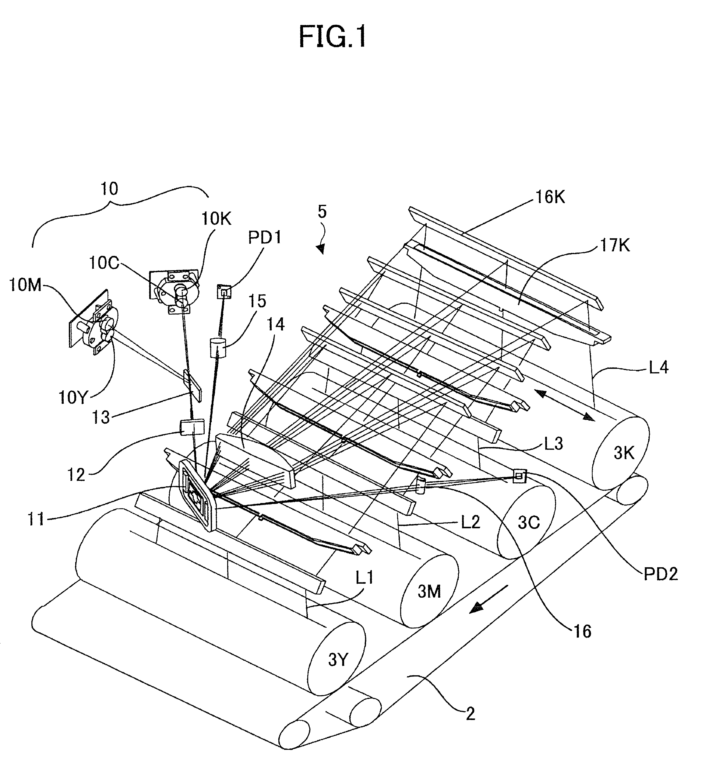
[0039]FIG. 1 is a perspective view showing a configuration example of the optical scanner according to the embodiment of the present invention.

[0040]In this configuration example, the optical scanner 5 is arranged above an image forming section in an image forming apparatus shown in FIG. 9. In the image forming section, four photosensitive drums 3Y, 3M, 3C, and 3K (hereinafter additional characters Y, M, C, and K are added to corresponding reference numerals to differentiate them according to the colors of Y (yellow), M (magenta), C (cyan), and K (Black)) are provided side by side. Furthermore, the optical scanner 5 has four optical sources corresponding to the colors, an optical deflection unit (vibration mirror 11) by which laser beams from the optical sources are deflected to scan, and a scanning image-forming optical system that directs the laser beams o...


PUM


Abstract

An optical scanner is disclosed that has an optical source unit that emits a laser beam; a vibration mirror by which the laser beam from the optical source unit is deflected to scan; a driving circuit that vibrates the vibration mirror based on a driving signal generated from a reference clock; a light-receiving element that receives the laser beam within the scanning area of the laser beam; and a controlling unit that corrects the driving signal so as to make a phase deviation between the reference phase clock and the output signal of the light-receiving element constant.

Description

BACKGROUND OF THE INVENTION[0001]1. Field of the Invention[0002]The present invention relates to an optical scanner having a vibration mirror used for a laser raster writing optical system and a color image forming apparatus.[0003]2. Description of the Related Art[0004]Up until now, in order to allow a color image forming machine to perform high-speed printing and realize high image quality, it is required that a polygon scanner rotate at a high speed of 25000 rpm or more and with high accuracy. On the other hand, the high image quality can be obtained with the reduction of the diameter of a laser beam. Therefore, the radius of the inscribed circle and the length in the main scanning direction of a polygon mirror used for the polygon scanner become relatively large, which results in an increase in the load of the polygon scanner.[0005]When the load of the polygon scanner increases, its consumption power increases and heat generated by the polygon scanner adversely affects optical el...

Claims


Application Information

Patent Timeline
Patent Type & Authority Patents(United States)
IPC IPC(8): G02B26/08G02B26/10G02B26/12
CPCG02B26/105
Inventor SUZUKI, MITSUOSATOH, MASAKISUZUKI, HARUYUKI
Owner RICOH KK
Why Eureka
Try Eureka