
Planer

a hand-held, battery-powered technology, applied in the direction of hand planes, dynamo-electric machines, flat surfacing machines, etc., can solve the problems of low iron loss, 62/b> made of laminated steel would be more difficult and therefore more costly to make than one made of soft iron composi

Active Publication Date: 2012-03-20
BLACK & DECKER INC
View PDF19 Cites 12 Cited by
  • Summary
  • Abstract
  • Description
  • Claims
  • Application Information

AI Technical Summary

Benefits of technology

This design enhances user comfort and tool stability by effectively damping vibrations, allowing for smoother operation and reduced risk of damage to the workpiece.

Problems solved by technology

Overall, the extremely low iron loss due to eddy currents is comparable to that of laminated steels, however claw pole members 60, 62 made from laminated steel would be more difficult and therefore more costly to make than one made of the soft iron composite.

Method used


Image

  • Planer
  • Planer
  • Planer

Examples


Embodiment Construction

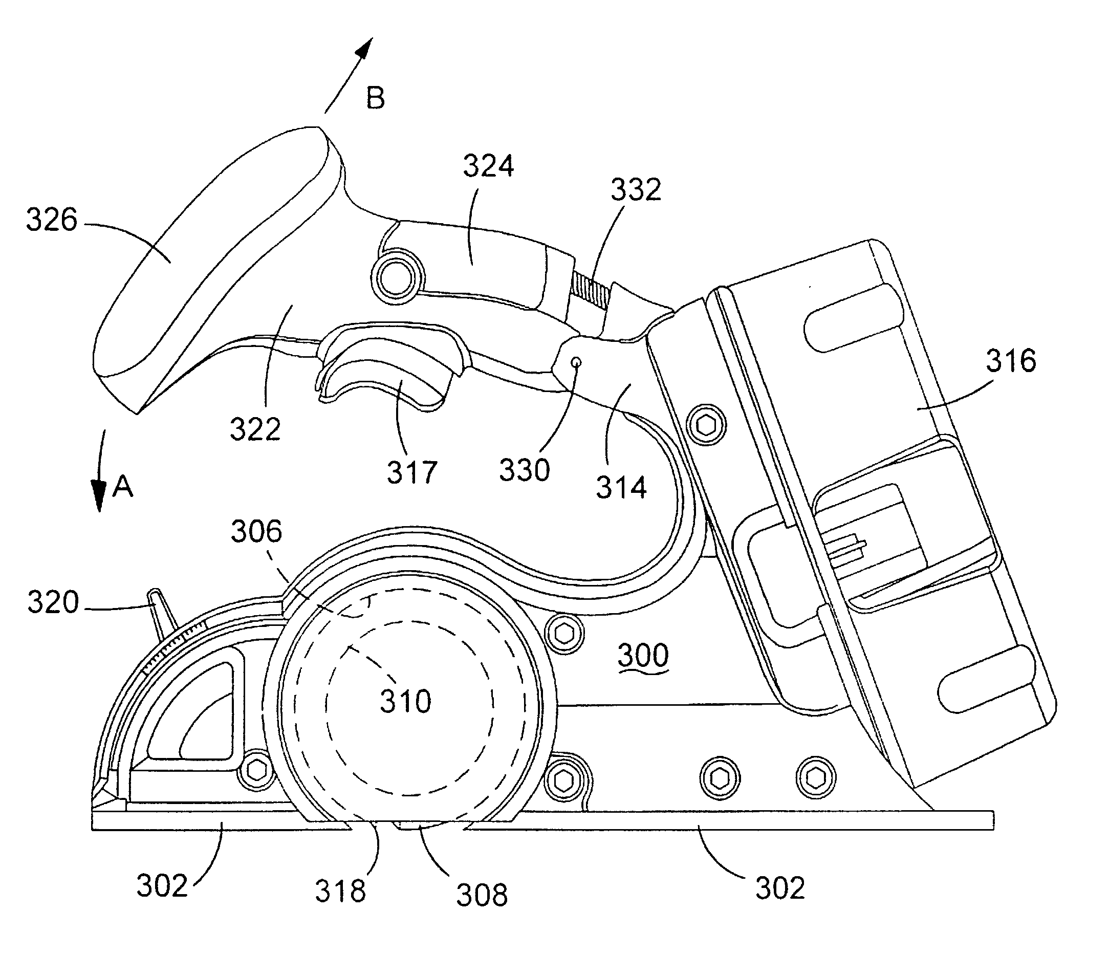
[0036]Referring to FIGS. 13 to 16, the hand held electrically power planer includes a housing 300. Attached to the underside of the housing 300 is a work piece engaging shoe 302 through which is formed an aperture 304. The shoe 302 rests against a work piece when the planer is in use. Rotatably mounted within the housing 300 is a cutting drum (indicated by dashed lines 306 in FIG. 16). A part 308 of drum 306 protrudes through the aperture 304 in the shoe 302. A cutting blade 318 is rigidly attached to the drum 306. An electric motor (indicated by dashed lines 310 in FIG. 16) is mounted within the housing 300. The motor 310 rotatingly drives the cutting drum 306 via a rubber belt (shown by dashed lines 312 in FIG. 16) when activated in a similar manner to the planer described previously with reference to FIG. 1. The motor is powered by a battery pack 316 releasably mounted on to the rear 314 of the housing 300. The battery 316 is in electrical contact with the motor 310 via a trigger...


PUM


Abstract

A hand held electrically powered planer including a housing; an electric motor mounted within the housing; a work piece engaging shoe mounted on the underside of the housing having an aperture formed therethrough; and a cutting drum rotatably mounted within the housing, which is capable of being rotatably driven by the electric motor when the electric motor is activated. A part of the cutting drum protrudes through the aperture to engage a work piece. A cutting blade is mounted on the cutting drum. A rear handle is mounted on the housing and includes an elongate shaft attached at one end only to the rear of the housing and extends forward in a lengthwise direction over a portion of the housing toward the front end of the housing. A grip is mounted or formed on the elongate shaft and there is a front handle which is mounted on the free end of the shaft forward of the grip.

Description

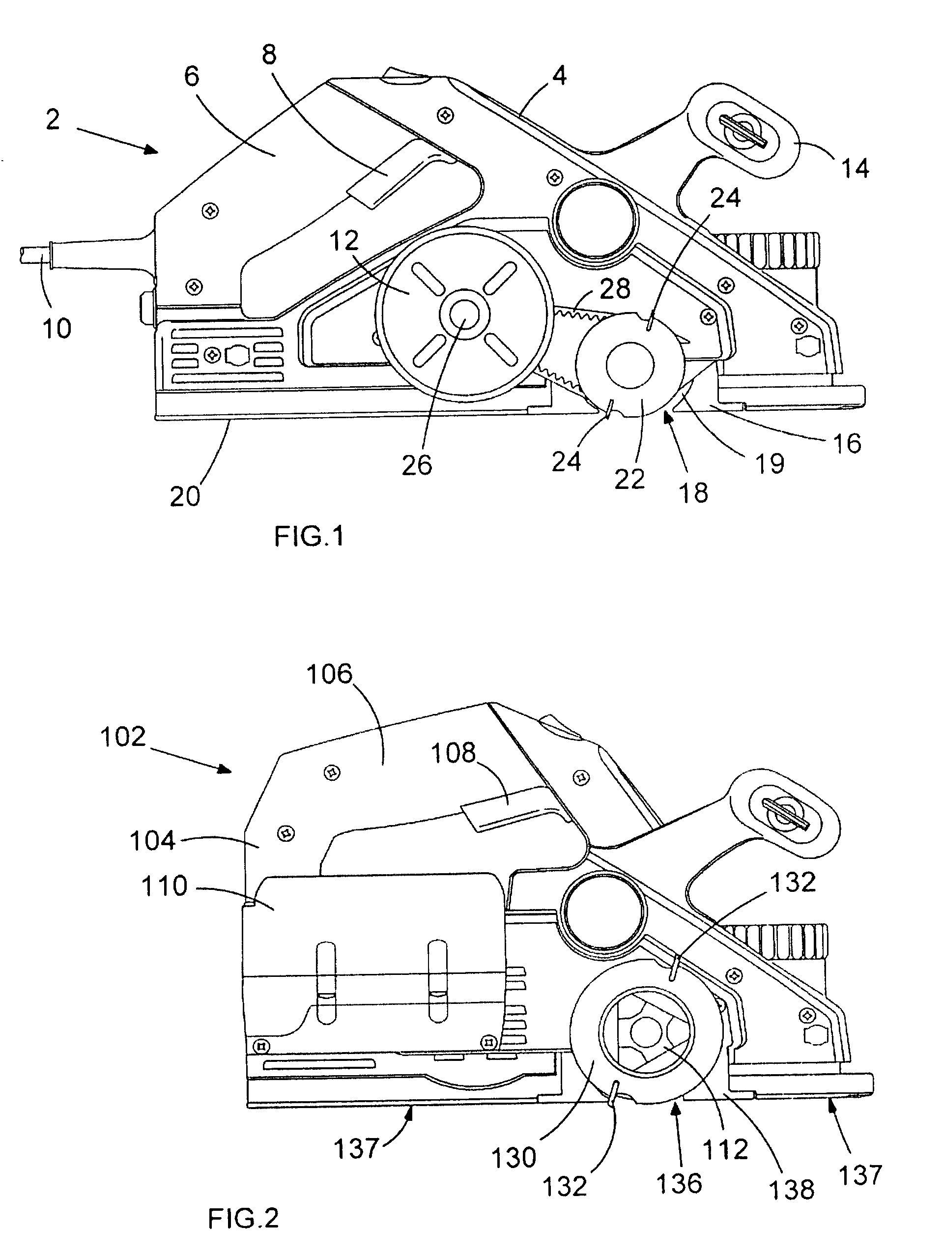
FIELD OF THE INVENTION[0001]The present invention relates to a battery powered hand held planer.BACKGROUND OF THE INVENTION[0002]A known type of hand held planer for removing the surface of a workpiece such as a wooden door is shown in FIG. 1. The planer 2 has a housing 4 having a rear handle 6, provided with a trigger switch 8 for supplying electrical power via a power supply cable 10 to an electric motor 12, and a front handle 14. A shoe 16 having a part-cylindrical recess 19 is mounted to and flush with the bottom 20 of the housing 4. A planer cylinder 22 having a pair of diametrically opposed blades 24 is rotatably mounted in the recess 19 so that the surface of the planer cylinder 22 protrudes slightly from the recess 19 through an aperture 18 in the underside of the shoe 16 in order to engage a workpiece (not shown) when the planer 2 rests on the workpiece. The motor 12 has an output shaft 26 which is connected via a drive belt 28 to the planer cylinder 22 such that the planer...

Claims


Application Information

Patent Timeline
Patent Type & Authority Patents(United States)
IPC IPC(8): B27C1/10
CPCB27C1/10B25F5/006H02K1/145
Inventor ROSENAU, ISABELLBELL, IAN
Owner BLACK & DECKER INC
Learn More