Telescopic pull-out arrangement

a technology of pull-out arrangement and telescopic extension, which is applied in the field of telescopic pull-out arrangement, can solve the problems of reducing the stability of the storage section of the telescopic extension slide, affecting the performance of the extension slide, and unable to compensate the dimensional tolerance. achieve the effect of compensating the dimensional toleran

Inactive Publication Date: 2012-03-27
BSH BOSCH & SIEMENS HAUSGERAETE GMBH +1
View PDF14 Cites 5 Cited by
  • Summary
  • Abstract
  • Description
  • Claims
  • Application Information

AI Technical Summary

Benefits of technology

[0006]The object of the present invention is to resolve this dilemma by creating a telescopic pull-out arrangement with two telescopic extension slides, each having a fixed rail and at least one movable rail mounted to a common frame, and a storage section which is held on the movable rails via at least one pair of adapters, wherein, on the one hand, the storage section can be fixed despite the identicalness of the adapters and, on the other hand, dimensional tolerances can be compensated.

Problems solved by technology

Although an intermediate rail of this kind enables a freedom of movement of the telescopic extension slide to be achieved that is greater than the length of each of its individual rails, when pulled apart the movable rails may also swing back and forth transversely to the pull-out direction, which compromises the stability of the storage section on the telescopic extension slides.
However, this play must be limited in order to ensure that, in the pulled-out configuration, the storage section still rests securely on the rails and cannot slide off.
If the storage section and adapters engage in one another in a tightly toleranced manner, dimensional tolerances can no longer be compensated.
Resultant stressing of the telescopic extension slides in the horizontal direction transversely to the pull-out direction puts considerable wear and tear on the extension slides.
However, if transverse play with respect to the pull-out direction is provided between the storage section and the two adapters, the storage section as a whole will no longer be firmly anchored.

Method used


Image

  • Telescopic pull-out arrangement
  • Telescopic pull-out arrangement
  • Telescopic pull-out arrangement

Examples


Embodiment Construction

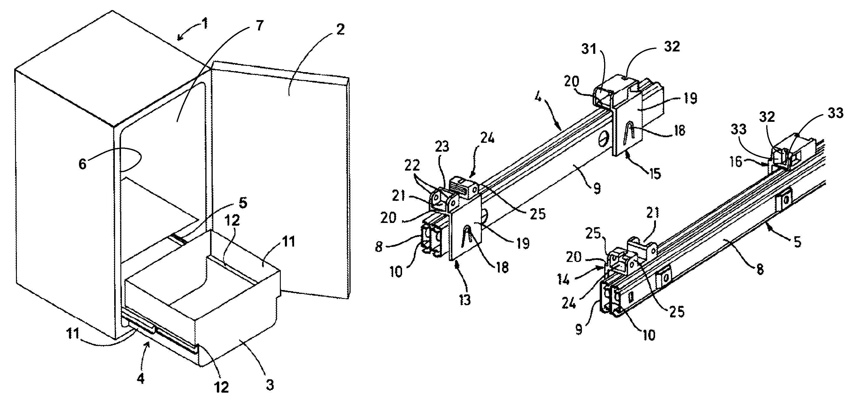
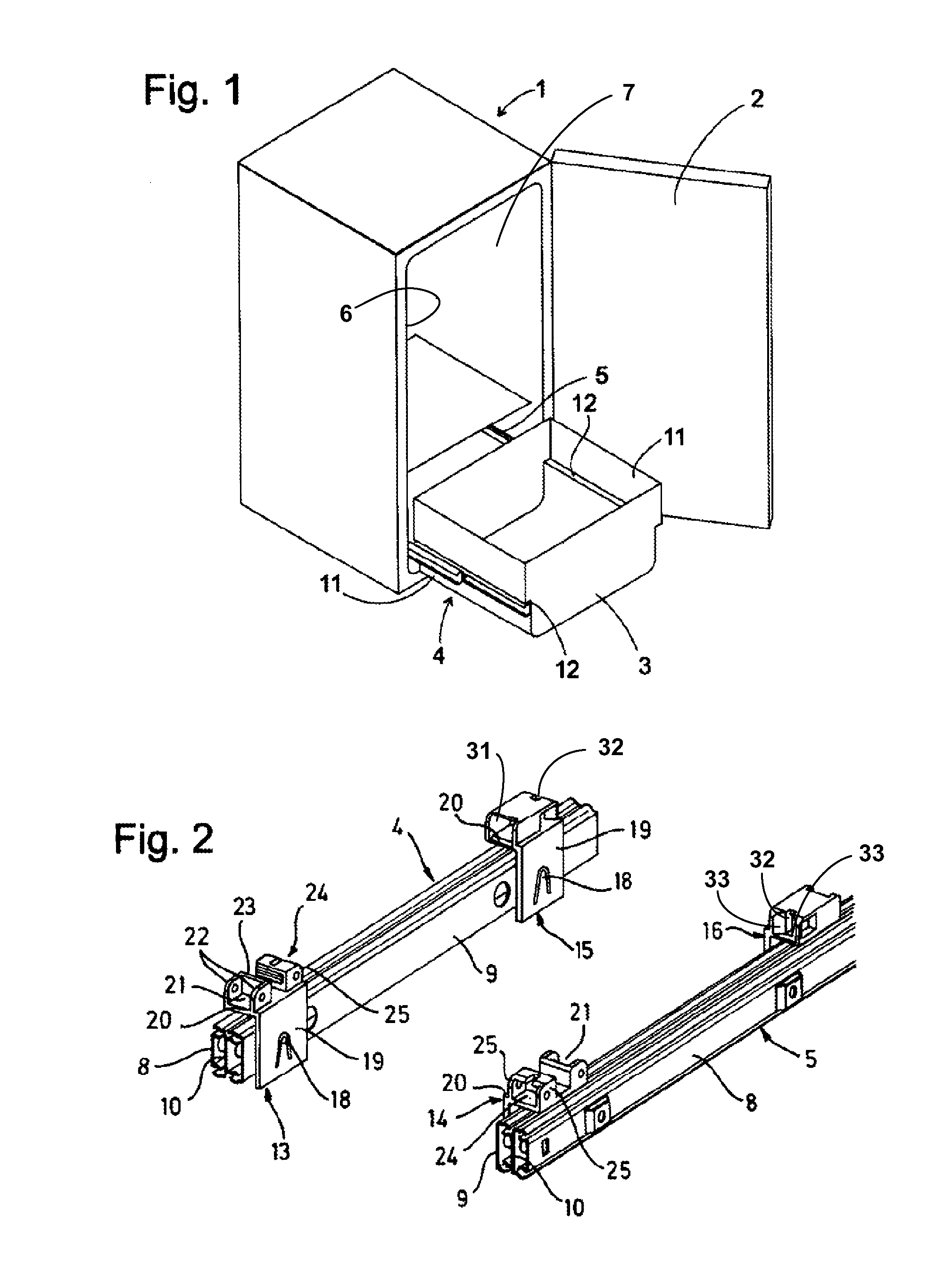
[0027]FIG. 1 shows a simplified perspective view of a refrigerator with a body 1 and a door 2, in the interior of which is mounted a telescopic pull-out arrangement with a pull-out box 3 shown pulled out. The pull-out box is retained by a left-hand telescopic extension slide 4 and a right-hand telescopic extension slide 5. The telescopic extension slides 4, 5 are implemented here as full extension slides, with a fixed rail 8 anchored to a side wall 6 and 7 respectively of the body 1 (see FIG. 2), a rail 9 supporting the pull-out box 3 and movable therewith, and an intermediate rail 10 which couples the fixed rail 8 and the movable rail 9 to one another. Alternatively, part extension slides could also be used for the telescopic extension slides 4, 5.

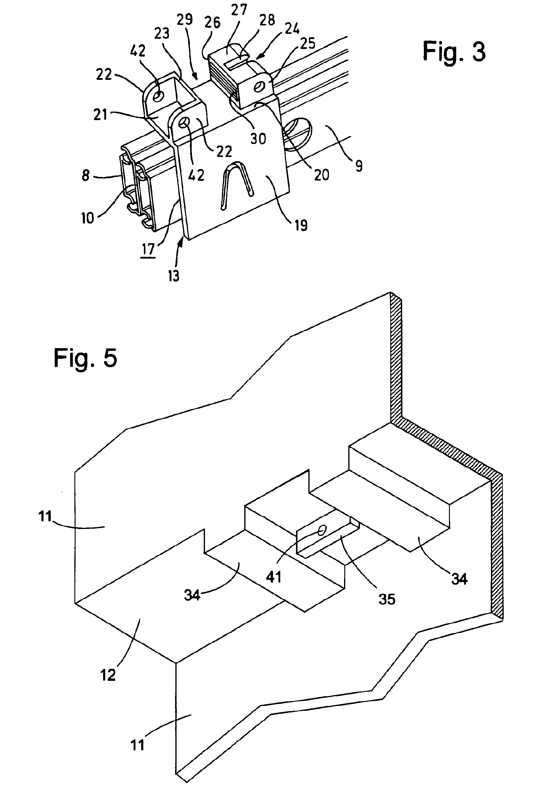
[0028]The pull-out box 3 has two side walls 11 in which a horizontal shoulder 12 is formed in each case. These shoulders 12 rest on the movable rails 9 of the telescopic extension slides 4, 5. These shoulders 12 must on the one hand be as...


PUM


Abstract

A telescopic pull-out arrangement for a refrigerator is provided that includes two telescopic pull-out mechanisms each provided with a stationary rail on a common frame and a movable rail, and a storage part retained on the movable rails by a pair of identical adapters. The storage part has a first engagement contour cooperating with a first adapter of the couple and a second engagement contour cooperating with the second adapter of the couple. Each adapter is provided with a third and a fourth engagement contour. The first engagement contour of the storage part and the third engagement contour of the first adapter engage into one another with less tolerance transverse to the pull-out direction than the engagement of the second engagement contour of the storage part and the fourth engagement contour of the second adapter engage into one another.

Description

BACKGROUND OF THE INVENTION[0001]The present invention relates to a telescopic pull-out arrangement comprising two telescopic extension slides, each having a fixed rail and at least one movable rail mounted to a common frame, and a storage section, such as a tray or box, which is held on the movable rails via at least one pair of adapters. Such a telescopic pull-out arrangement, used for retaining and guiding a pull-out box in a refrigerator, is described e.g. in DE 10 2005 021 591 A1.[0002]Telescopic extension slides are known in the form of part extension slides and full extension slides. A part extension slide comprises a pair of rails that can move counter to one another. As the rails must not completely disengage when they are pulled apart, the freedom of movement of the rails of a part extension slide relative to one another is less than their length.[0003]In order to achieve greater freedom of movement, full extension slides are used. These comprise, between a fixed rail and ...

Claims


Application Information

Patent Timeline
Patent Type & Authority Patents(United States)
IPC IPC(8): A47B88/00A47B96/04A47B88/49
CPCA47B88/0422F25D25/024A47B2088/0444A47B88/427A47B2088/4235
Inventor PLACKE, FRANKRUPP, CLAUDIASTAHL, MATTHIASVAN PELS, ULRICH
Owner BSH BOSCH & SIEMENS HAUSGERAETE GMBH
Why Eureka
Try Eureka