Clutch device for a motor vehicle

A clutch device, a technology for motor vehicles, applied in the direction of mechanical drive clutches, clutches, friction clutches, etc., can solve the problem of frequent

Active Publication Date: 2018-07-31
VALEO EMBRAYAGES SAS
View PDF5 Cites 1 Cited by
  • Summary
  • Abstract
  • Description
  • Claims
  • Application Information

AI Technical Summary

Problems solved by technology

For such vehicles, the electric mode is used more frequently than the thermal mode

Method used


Image

  • Clutch device for a motor vehicle
  • Clutch device for a motor vehicle
  • Clutch device for a motor vehicle

Examples


Embodiment Construction

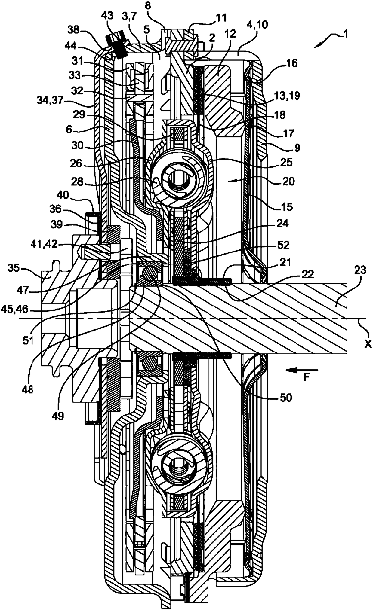
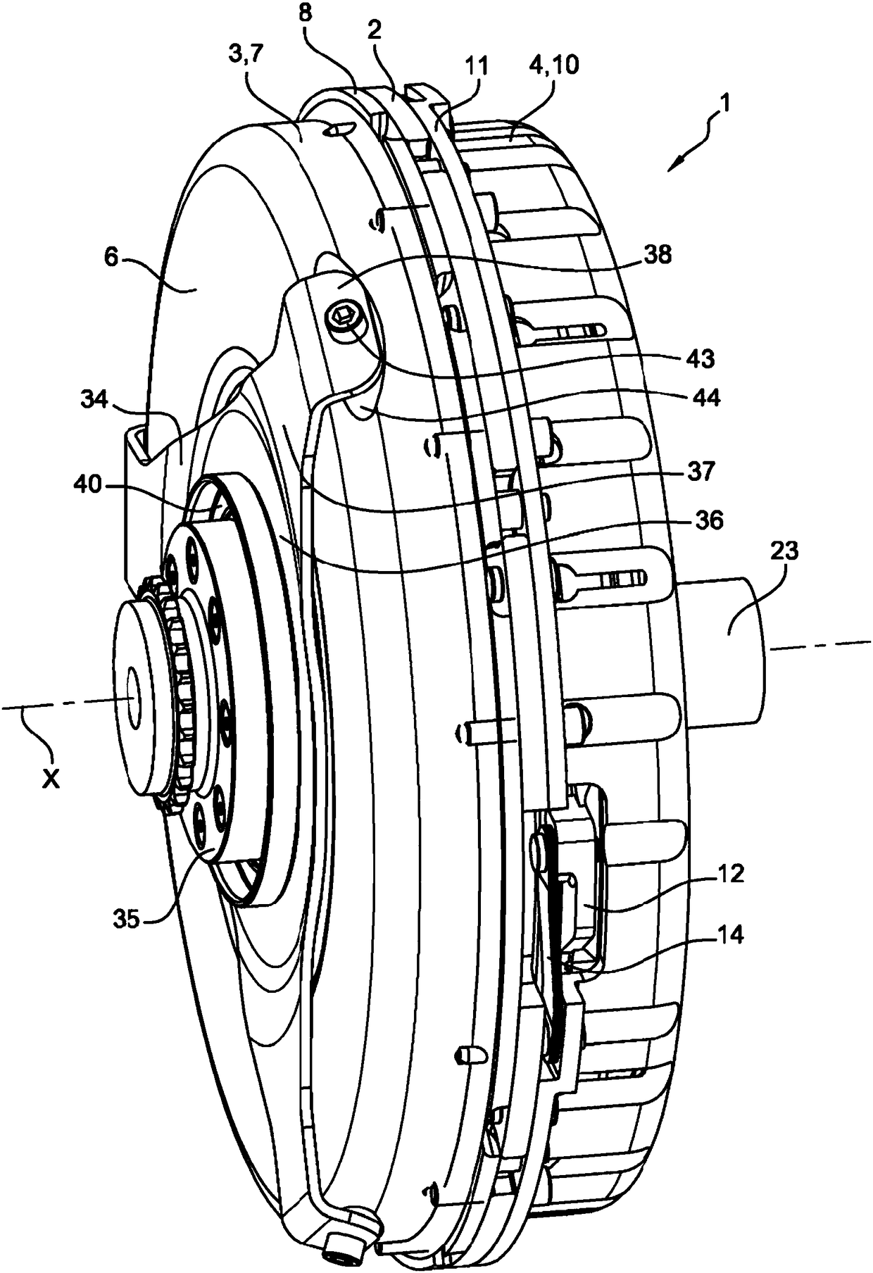
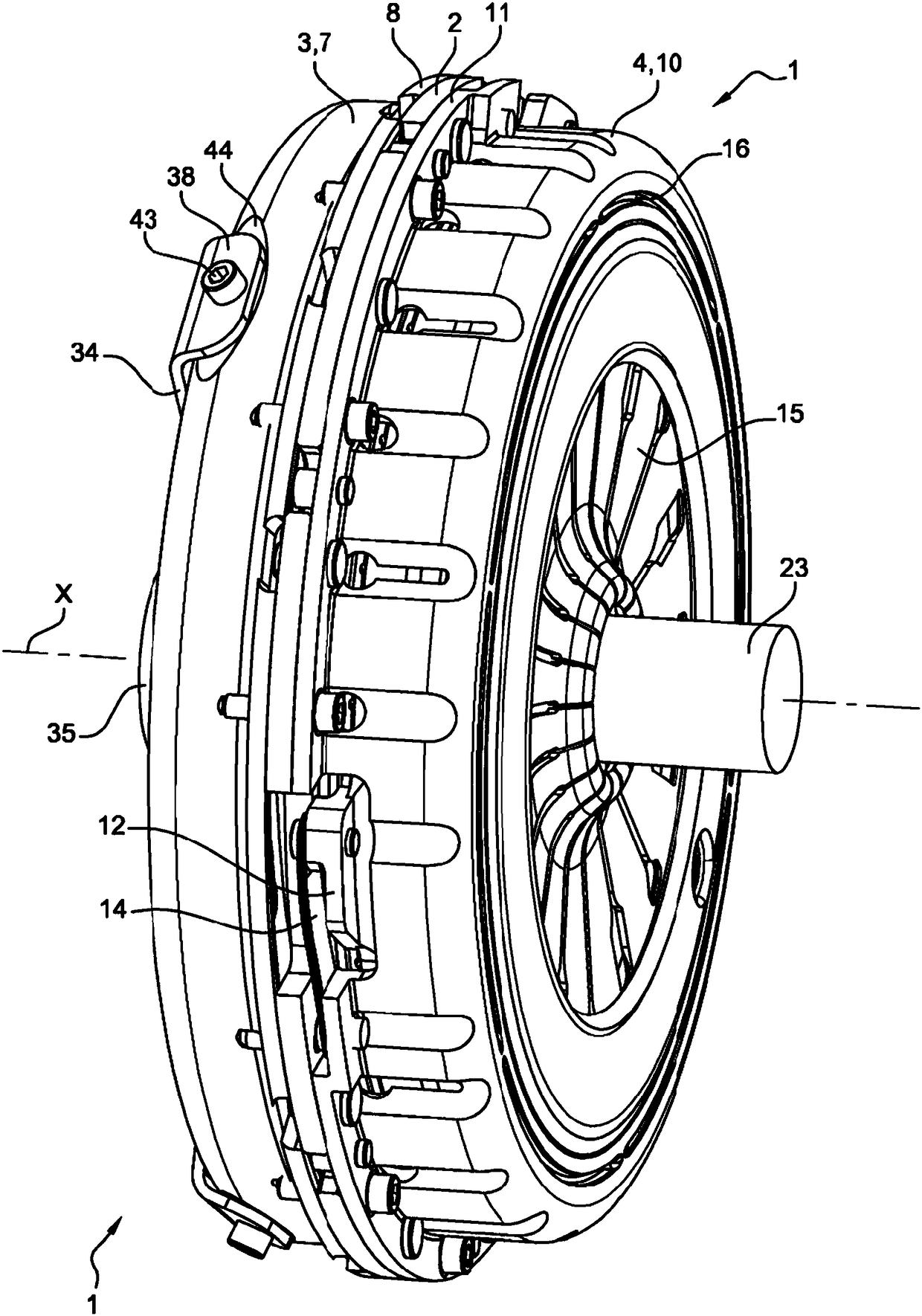
[0044] A clutch device 1 for a motor vehicle according to an embodiment of the present invention is Figures 1 to 7shown in . It comprises an annular reaction plate 2 with axis X, the radially outer periphery of which is connected at the rear to the radially outer periphery of a bell-shaped annular flywheel 3 and at the front to the radially outer periphery of a bell-shaped cover 4 around. The flywheel 3 and the cover 4 delimit an internal volume 5 .

[0045] The flywheel 3 comprises a radially extending rear portion 6 and a forwardly extending cylindrical portion 7 at the radially outer periphery. The front end of the cylindrical portion 7 comprises radial flanges 8 or tabs, which are fastened to the reaction plate 2, for example by rivets.

[0046] The cover 4 comprises a radially extending front portion 9 and a rearwardly extending cylindrical portion 10 at the radially outer periphery. The rear end of the cylindrical part comprises radial flanges 11 or tabs, which are ...


PUM


Abstract

The invention concerns a clutch device (1) for a motor vehicle, comprising a reaction plate (2) intended to be rotatably coupled to a crankshaft (35), a friction disk (13) intended to be coupled to aninput shaft (23) of a gearbox, a pressure plate (12) actuated by a diaphragm (15), so as to tighten or release the friction disk (13) on the reaction plate (2), damping means (20) mounted between thefriction disk (13) and the input shaft (23) of the gearbox, the damping means (20) acting against the rotation of the friction disk (13) relative to the input shaft (23) of the gearbox.

Description

technical field [0001] The invention relates to a clutch arrangement for a motor vehicle. Background technique [0002] A clutch arrangement traditionally comprises a reaction plate intended to be coupled in rotation to the crankshaft of the engine of the vehicle, a friction plate intended to be coupled to the input shaft of the gearbox, and a pressure plate. The movement of the pressure plate is controlled by a diaphragm, which is itself controlled by the clutch thrust bearing. [0003] The pressure plate is thus movable between an engaged position, in which the friction disk is clamped between said pressure plate and the reaction plate, and a disengaged position, in which the friction disk is released. [0004] A damping device is usually mounted between the input shaft of the gearbox and the friction disc, the damping device acting against the rotation of the friction disc relative to the gearbox input shaft. [0005] During operation, the clutch thrust bearing exerts a...

Claims


Application Information

Patent Timeline
Patent Type & Authority Applications(China)
IPC IPC(8): F16D13/71F16D3/79
CPCF16D3/79F16D13/71
Inventor G.勒巴斯T.拉福热
Owner VALEO EMBRAYAGES SAS
Why Eureka
Try Eureka