Method for fastening permanent magnet in rotor core of motor

A rotor core and permanent magnet technology, applied in the field of motors, can solve problems such as difficult installation, complicated installation process, and negative influence of magnetic flux

Pending Publication Date: 2021-06-08
慕贝尔汽车部件(太仓)有限公司
View PDF0 Cites 0 Cited by
  • Summary
  • Abstract
  • Description
  • Claims
  • Application Information

AI Technical Summary

Problems solved by technology

[0002] In the traditional surface permanent magnet structure of electric motors, the permanent magnets are usually fixed by gluing or resin embedding, bonding the permanent magnets in the rotor core or embedding the permanent magnets in the rotor core, which not only There are defects such as complex installation process, high installation difficulty and high cost. At the same time, it is necessary to reserve space for adhesive or resin between the iron core and the permanent magnet. In the case of strong vibration and heat, the adhesive or resin is prone to failure Aging can easily cause permanent magnets to shift or even fall off in the circumferential direction, which will have a greater negative impact on the magnetic flux

Method used


Image

  • Method for fastening permanent magnet in rotor core of motor
  • Method for fastening permanent magnet in rotor core of motor
  • Method for fastening permanent magnet in rotor core of motor

Examples


Embodiment Construction

[0041] In order to make the technical problems, technical solutions and beneficial effects to be solved by the present invention clearer, the present invention will be further described in detail below in conjunction with the accompanying drawings and embodiments. It should be understood that the specific embodiments described here are only used to explain the present invention, not to limit the present invention.

[0042] It should be noted that when an element is referred to as being “connected to” or “disposed on” another element, it may be directly on the other element or be indirectly on the other element. When an element is referred to as being "connected to" another element, it can be directly connected to the other element or indirectly connected to the other element.

[0043] In the description of the present invention, it should be noted that unless otherwise specified and limited, the terms "installation", "connection" and "connection" should be understood in a broa...


PUM


Abstract

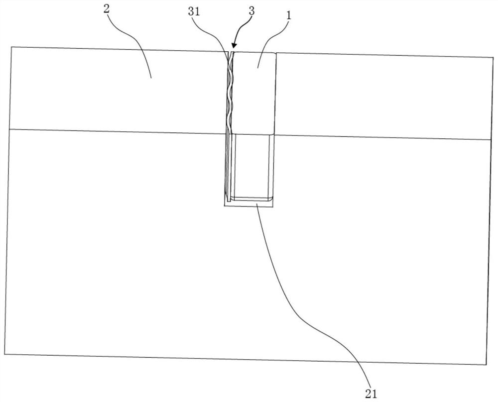
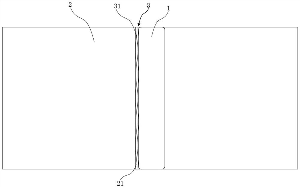
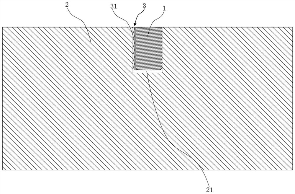
The invention provides a method for fastening a permanent magnet in a rotor core of a motor. According to the method, when the permanent magnet is to be fastened in the rotor core, only a mounting groove needs to be formed in the rotor core, the permanent magnet is accommodated in the mounting groove, a fastening element with a wave-shaped outer contour is arranged between one side wall of the mounting groove and the corresponding side surface of the permanent magnet in a separated manner so as to allow the fastening element with the wave-shaped outer contour to be not flattened under the condition that an assembling gap between the permanent magnet and the rotor iron core is the largest and to be flattened under the condition that the assembling gap between the permanent magnet and the rotor iron core is the smallest, and thus, the fastening element with the wave-shaped outer contour can be utilized to elastically abut against the permanent magnet so as to allow the permanent magnet to be efficiently installed and fastened in the mounting groove in the iron core of the rotor; and thus, the installation technology of the permanent magnet is simplified, and the installation difficulty of the permanent magnet is reduced. Moreover, dimensional tolerance between the iron core of the rotor and the permanent magnet can be effectively compensated, the gap between the mounting groove of the rotor iron core and the permanent magnet is effectively avoided, and negative influence on magnetic flux is reduced.

Description

technical field [0001] The invention belongs to the technical field of motors, and in particular relates to a method for fastening a permanent magnet in a rotor iron core of a motor. Background technique [0002] In the traditional surface-type permanent magnet structure of electric motors, the permanent magnets are usually fixed by gluing or resin inlays. The permanent magnets are bonded in the rotor core or the permanent magnets are embedded in the rotor core. This is not only There are defects such as complex installation process, difficult installation and high cost. At the same time, it is necessary to reserve space for adhesive or resin between the iron core and the permanent magnet. In the case of strong vibration and heat, the adhesive or resin is prone to failure Aging will easily cause the permanent magnets to shift or even fall off along the circumferential direction, which will have a great negative impact on the magnetic flux. Contents of the invention [000...

Claims


Application Information

Patent Timeline
Patent Type & Authority Applications(China)
IPC IPC(8): H02K15/03H02K1/28
CPCH02K1/28H02K15/03
Inventor 本杰明·登格斯曼弗雷德·舒尔特
Owner 慕贝尔汽车部件(太仓)有限公司
Why Eureka
Try Eureka