Building structure, method of making, and components

a technology of building structure and method, applied in the direction of building components, structural elements, building repairs, etc., can solve the problems of inelastic hinge formation in the beam, reduce the plastic moment capacity of the beam, and progress of entire buildings, so as to increase the strain of the beam, increase the volume and length of steel, and preserve building integrity and human life.

Active Publication Date: 2012-04-03
MITEK HLDG INC
View PDF28 Cites 34 Cited by
  • Summary
  • Abstract
  • Description
  • Claims
  • Application Information

AI Technical Summary

Problems solved by technology

Failures in a column, beams, and / or beam-to-column joint connection structures, and beam-to-beam joint connection structures, due to explosions, severe impact and / or sustained fire, have led to progressive collapse of entire buildings.
This alternative design reduces the plastic moment capacity of the beam allowing inelastic hinge formation in the beam to occur at the reduced section of the beam.
Accordingly, such joint connection structures can provide only a limited amount of post-blast residual gravity load-carrying capacity due to their inability to resist the gravity load demand of simultaneous moment and axial tension, which load interaction is the result of the formation of a “double-span” condition caused by two beams being connected to a common column which is then suddenly or violently removed or otherwise is severely compromised due to explosion, blast, impact or other events.
Additionally, none of these alternatives, except the gusset plates used as taught in the '017 patent, provide any significant torsion capacity or significant resistance to lateral bending to resist direct explosive air blast impingement and severe impact loads.

Method used


Image

  • Building structure, method of making, and components
  • Building structure, method of making, and components
  • Building structure, method of making, and components

Examples


Embodiment Construction

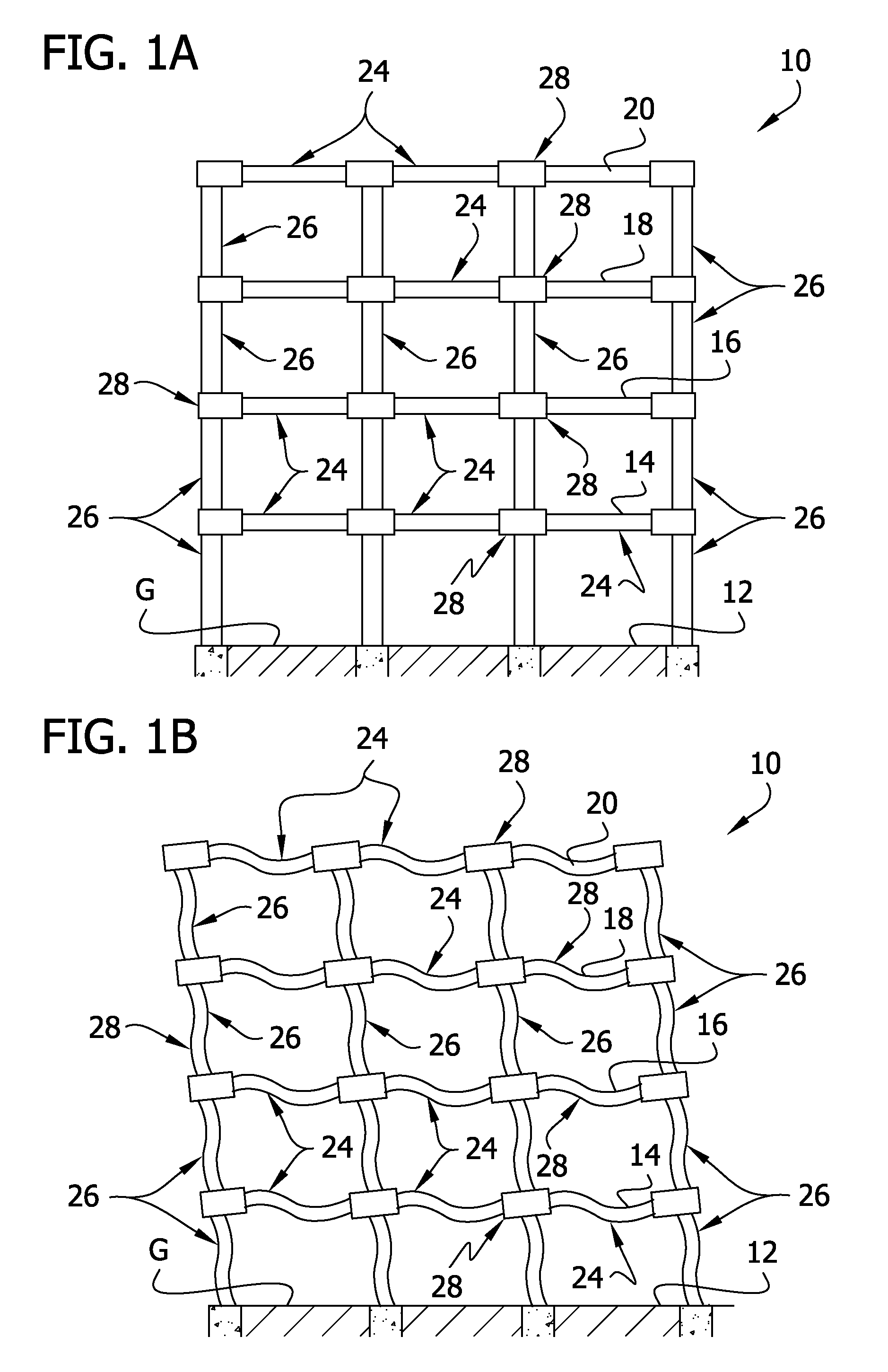
[0025]In broad overview, FIG. 1A provides a fragmentary diagrammatic elevation view of a framework 10 for a building. It will be understood by those ordinarily skilled in the pertinent arts that the framework 10 is three dimensional, although the elevation view does not illustrate this fact. In this instance, the framework 10 provides for a number of elevated floors and roof, indicated 14, 16, 18, and 20, each supported by generally horizontal beams. The beams are each generally indicated with the numeral 24. In order for the beams 24 to support the floors 14-18 and the roof 20, the building framework 10 includes plural spaced apart substantially vertical column assemblies, respectively and generally indicated with the numerals 26, each embedded into or supported upon a foundation (not seen in the drawing Figures but indicated as a ground plane “G” at which the ground floor 12 is located). It will be understood by those ordinarily skilled in the pertinent arts that the foundation ma...


PUM


Abstract

A building framework includes plural column assemblies supporting plural beams supporting floors of the building, with the union of the column assemblies and beams forming beam-to-column (or beam-to-column-to-beam) joint connection assemblies according to this invention. The joint connection assemblies inventively include novel features which remarkably and surprisingly improve the distribution of strain and plastic deformation in the joint connection structure when subjected to extreme load challenges to the building structure (as may occur during earthquake, explosion, progressive collapse load conditions, or massive impact.

Description

CROSS REFERENCE TO RELATED APPLICATION[0001]This application is a Continuation-in-Part of U.S. application Ser. No. 12 / 229,272, filed 21 Aug. 2008, and of U.S. application Ser. Nos. 12 / 315,666; 12 / 315,754; and 12 / 315,805, each filed 3 Dec. 2008, respectively; and incorporates by reference the disclosure of those earlier applications.BACKGROUND OF THE INVENTION[0002]Buildings, towers and similarly heavy structures commonly are built on and around a steel frame work. This steel framework generally includes substantially vertical columns supporting substantially horizontal beams, with the beams supporting building floors. A primary structural consideration of such a steel framework is the plural joint connections of the beams to the columns and to one another. An improved structural joint connection is disclosed in U.S. Pat. No. 5,660,017 (hereinafter, “the '017 patent”). However, advanced stress analysis techniques and a study of building collapse mechanisms following seismic events, ...

Claims


Application Information

Patent Timeline
Patent Type & Authority Patents(United States)
IPC IPC(8): E04B1/19E04B1/38
CPCE04B1/2403E04H9/02E04B2001/2415E04B2001/2442E04B2001/2448E04B2001/2496E04B2001/2445
Inventor KARNS, JESSE
Owner MITEK HLDG INC
Why Eureka
Try Eureka