Integration of vertical adjustability in an electric strike

Active Publication Date: 2012-04-17
HANCHETT ENTRY SYST INC AZ CORP
View PDF29 Cites 18 Cited by
  • Summary
  • Abstract
  • Description
  • Claims
  • Application Information

AI Technical Summary

Benefits of technology

[0009]It is the object of the present invention to provide a new and useful means to align the horizontal centerline of the guarded latch pathway in a dual ramping faceplate of an electric strike with the centerline of the latch bolt. Another object of this invention is to provide a compact electric strike that may be installed without modification in the doorframe or dust box of a door having standard ANSI 4 ⅞″ metal frame or ANSI/BHMA A 156/115-W metal frame.
[0010]Another object to this invention is to provide a compact electric strike design that will minimize the installation process for a standard aluminum frame, by requir

Problems solved by technology

Normal electric strikes of the type that ramp the latch bolt back into the door or closure do not provide allowance for vertical adjustment to align the strike with the centerline of the latch bolt contained in the door.
A

Method used


Image

  • Integration of vertical adjustability in an electric strike
  • Integration of vertical adjustability in an electric strike
  • Integration of vertical adjustability in an electric strike

Examples


Example

[0021]The same numerals are used throughout to designate the same or similar components with a letter appended in some cases for delineation.

DETAILED DESCRIPTION OF THE DRAWINGS

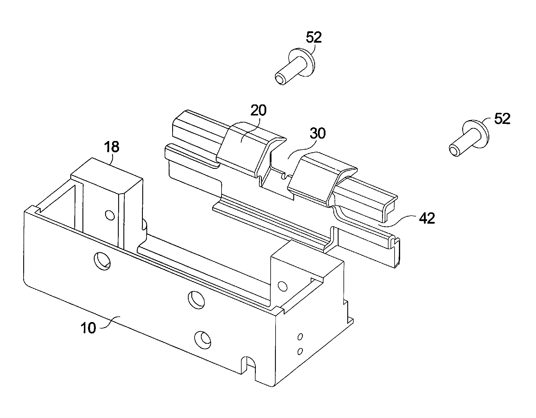
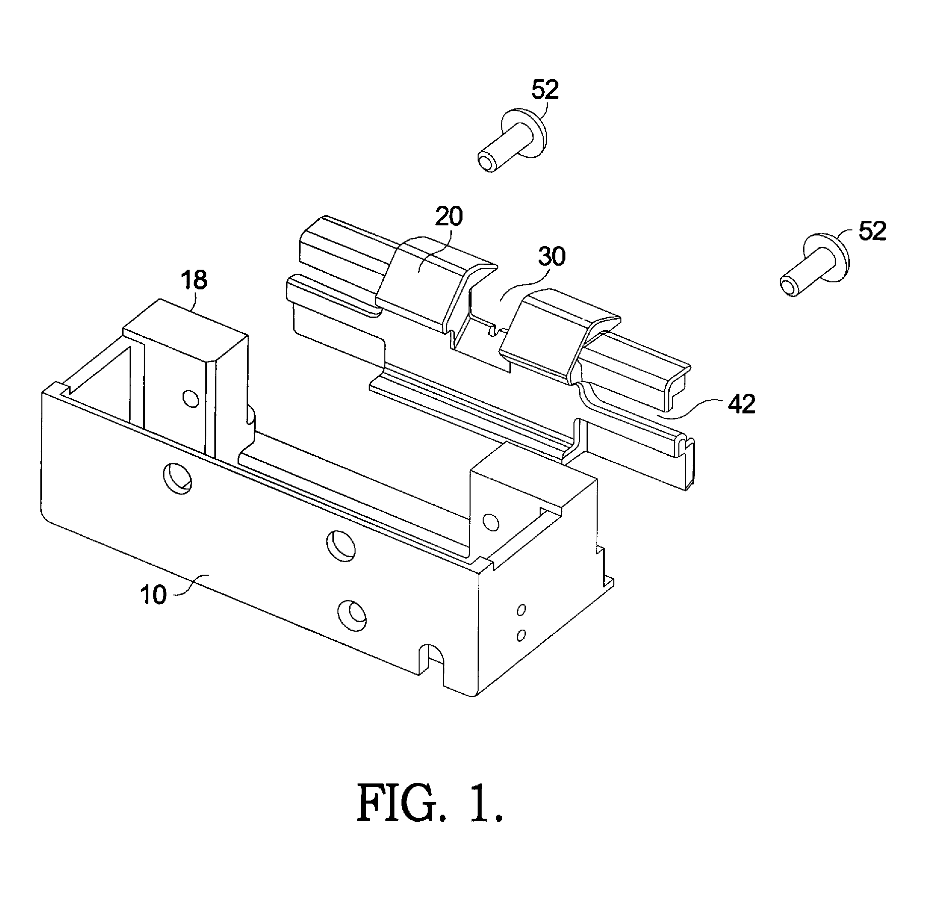
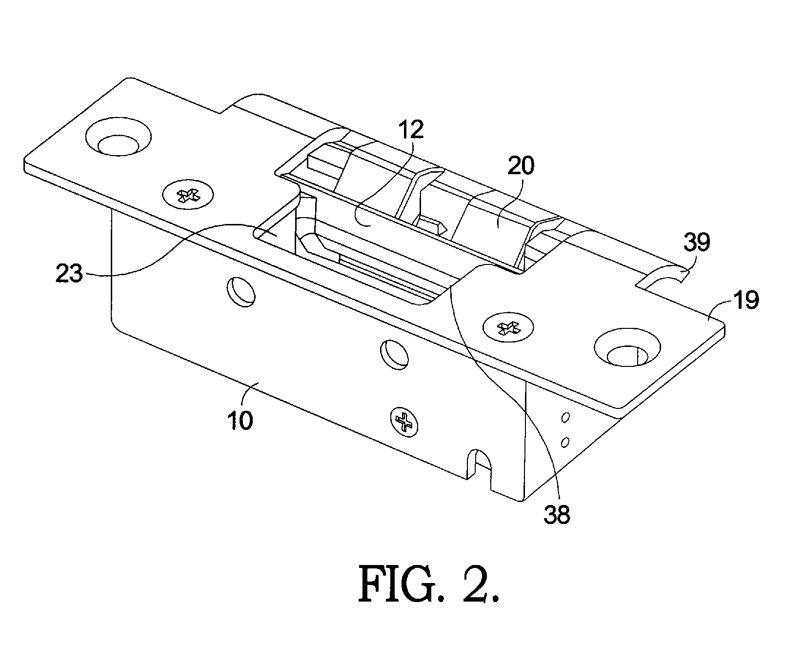
[0022]To release a latch bolt equipped with a dead latch, the electric strike must first release the dead latch to allow the latch bolt to become depressed into the door. The strike must also provide a pathway or slot to allow the extended dead latch to pass without interference as the door opens. To function properly, the electric strike, the dead latch and the latch bolt must be in proper vertical alignment.

[0023]It is common that door and frame installations for the door and frame are not installed perfectly square and aligned on center, thus causing the horizontal centerline of the latch bolt and strike to be misaligned as much as ¼″ above the centerline or ¼″ below the centerline of the strike. This situation can be further compounded by door sag in the frame occurring after installation.

[0024]The presen...


PUM


Abstract

An electric strike which provides vertical adjustability of the position of the strike relative to the latch bolt in the closure with modification to the doorframe on the dust box. A ramp element on the strike housing is slidably adjustable relative to the strike housing and is securable at the time of installation to align with the center of the latch bolt. The ramp element has a channel to allow entry and exit of a latch bolt having a dead latch. A keeper engages the dead latch and maintains it in a retracted position when the closure is locked and is released when the electric latch solenoid is energized. A travel limiting foot limits rotation of the keeper so that the latch bolt may transition from the keeper to the ramp element without interference.

Description

CROSS REFERENCE IS MADE TO RELATED APPLICATION[0001]This application is a continuation-in-part of U.S. patent application Ser. No. 12 / 057,091, filed Mar. 27, 2008, of the same title, which is based on U.S. Provisional Patent Application Ser. No. 60 / 920,736, filed Mar. 28, 2007, of the same title.FIELD OF THE INVENTION[0002]The present invention relates to security devices, and more particularly, to a concealed electric operated door strike for closures using latch bolts.BACKGROUND OF THE INVENTION[0003]In door or closure openings it may be desirable to automatically release locks having latch bolts or guarded latch bolts from their engagement in the door frame. Latch bolts are carried by a closure such as a door and are received in a strike which is mounted in a recess in a door frame. Guarded latch bolts are comprised of two elements: a latch bolt and a dead latch or latch guard. The dead latch is located directly adjacent the latch bolt and follows the latch bolt as the door or cl...

Claims


Application Information

Patent Timeline
IPC IPC(8): E05B15/02
CPCE05B47/0047E05B15/0245E05B55/005Y10T292/696Y10T292/68Y10T292/707Y10T292/702Y10T292/699
Inventor WEBB, MICHAEL A.PEABODY, JOSHUA T.SULLIVAN, SCOTTWHISEL, STEVE
Owner HANCHETT ENTRY SYST INC AZ CORP
Why Eureka
Try Eureka