Throwing disc

a technology of discs and discs, applied in the field of discs, can solve the problems of lack of engineering in the gyroscopic and metamorphic principles, and achieve the effects of reducing weight, maximizing flight quality, and reducing profil

Active Publication Date: 2012-04-17
COWLES WILLIAM +1
View PDF11 Cites 2 Cited by
  • Summary
  • Abstract
  • Description
  • Claims
  • Application Information

AI Technical Summary

Benefits of technology

[0008]It is another object of the present invention to provide an elliptical throwing disc which achieves significant reduction in weight and maximizes the quality of flight.
[0009]It is a further object of the present invention to provide a non-round throwing disc which has a thinner and / or flatter profile than the well known and popular Frisbee™ and Aerobie™ throwing discs.
[0010]It is yet a further object of the present invention to define a throwing disc which is easier to hold and throw with improved accuracy than conventional throwing discs.
[0011]It is still a further object of the present invention to provide an elliptical throwing disc which has better aerodynamic characteristics suited for throwing and catching sport than well known and popular throwing discs.
[0012]It is still another object of the present invention to provide an elliptical throwing disc which is less heavy and uses less wrist snap to impart necessary rotational forces to overcome weight parameters for flight than the popular Frisbee™ and Aerobie™ throwing discs.

Problems solved by technology

The elliptical design variations appear to not have been based on the required research to solve the very different aerodynamic geometries required of an elliptical throwing ring to have optimized flight characteristics, especially lacking engineering in the gyroscopic and metamorphic principles.

Method used


Image

  • Throwing disc
  • Throwing disc
  • Throwing disc

Examples


Embodiment Construction

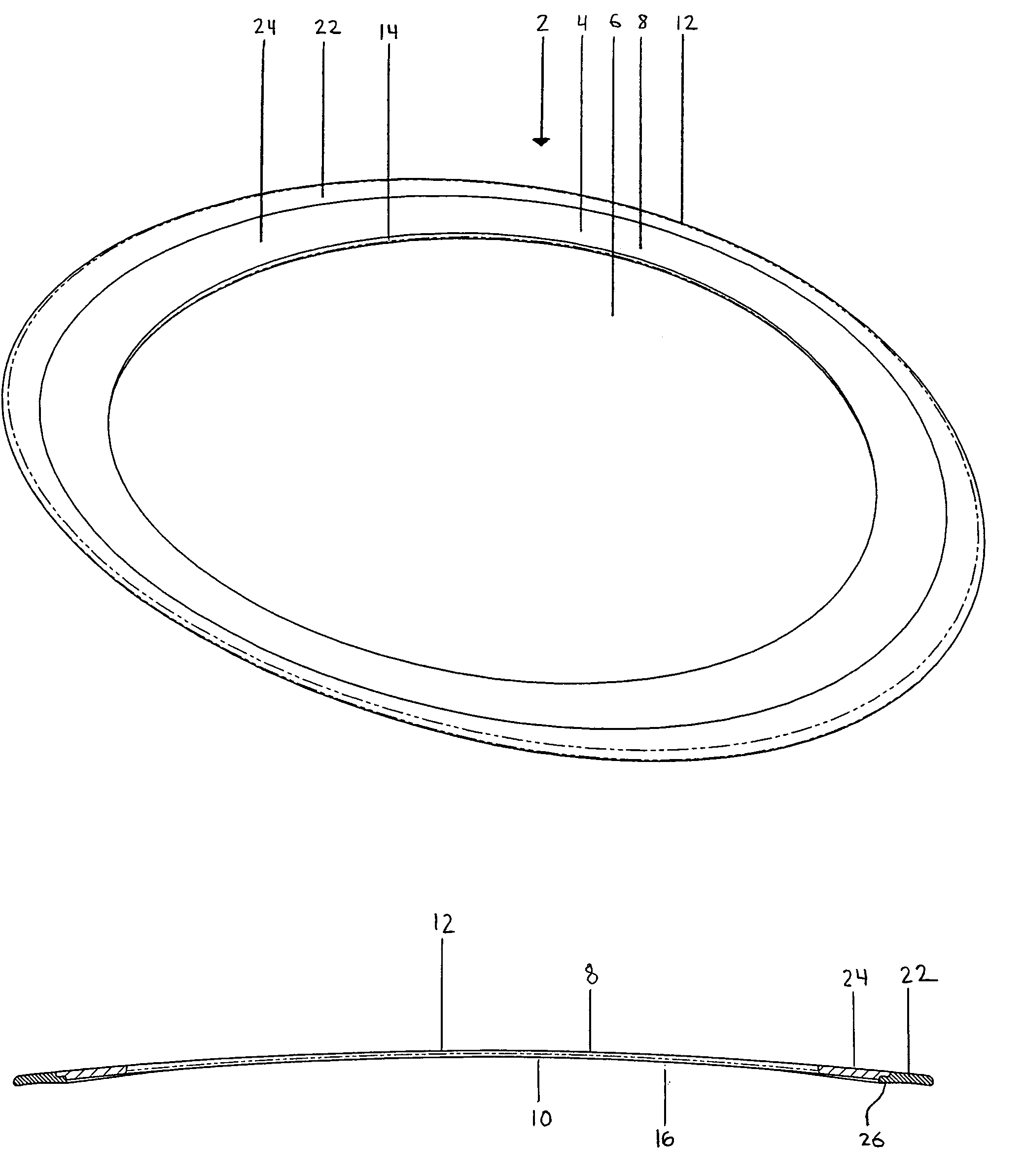
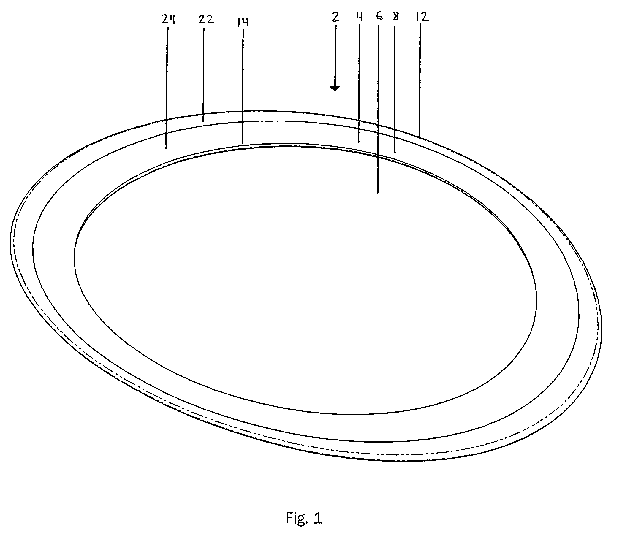
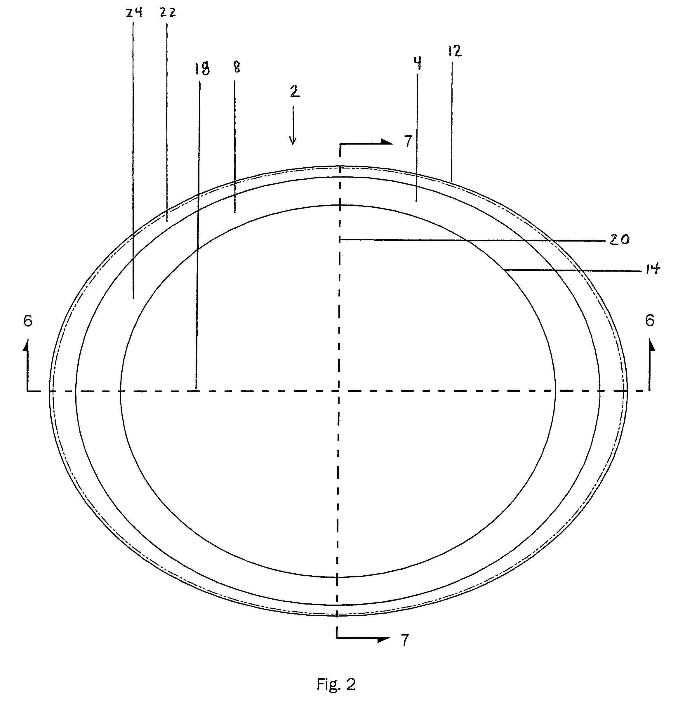
[0025]Referring initially to FIGS. 1-9 of the drawings, it will be seen that a throwing disc 2 constructed in one form of the present invention includes a non-round, continuous, flexible frame 4 which changes shape during flight. The flexible frame 4 defines a central opening 6 through the thickness thereof. The flexible frame 4 has a top side 8, a bottom side 10 opposite the top side, an outer peripheral edge 12 and an inner peripheral edge 14 situated radially inwardly of the outer peripheral edge 12. The flexible frame has an arched shape with a height that changes during flight. The arched shaped flexible frame 4 defines a three dimensional cavity 16 situated at the bottom side thereof to provide lift to the throwing disc 2 during flight.

[0026]In a preferred form of the invention, the flexible frame 4 of the throwing disc is generally oblong in shape, and includes a major axis 18 and a minor axis 20 situated perpendicularly to the major axis 18. Preferably, the flexible frame 4 ...


PUM


Abstract

A throwing disc includes an elliptical, continuous, flexible frame which changes shape during flight. The flexible frame defines a central opening through the thickness thereof. The flexible frame has an arched shape with a height that changes during flight and which defines a three dimensional cavity situated at the bottom side of the frame to provide lift to the throwing disc during flight.

Description

CROSS REFERENCE TO RELATED APPLICATION[0001]This application is related to U.S. Provisional Application Ser. No. 60 / 719,514 filed on Sep. 23, 2005, and entitled “Elliptical Throwing Ring”, the disclosure of which is incorporated herein by reference and on which priority is hereby claimed.BACKGROUND OF THE INVENTION[0002]1. Field of the Invention[0003]The present invention relates to throwing discs for recreational use.[0004]2. Description of the Prior Art[0005]Throwing discs are used for throwing and catching entertainment between two or more people. Two popular and well known throwing discs are commonly referred to by the trademarks Frisbee™ and Aerobie™. The Frisbee™ throwing disc is a circular disc in which the design characteristics occur in a single plane, that is, it exhibits a two dimensional shape that revolves about a central axis. Numerous geometric variations (i.e., leading edge, airfoil, rim, material, size and weight) for circular flying discs, such as the Frisbee™ thro...

Claims


Application Information

Patent Timeline
Patent Type & Authority Patents(United States)
IPC IPC(8): A63H27/00
CPCA63H33/18A63H33/22
Inventor COWLES, WILLIAMDIMOTTA, WILLIAM
Owner COWLES WILLIAM
Why Eureka
Try Eureka