Encasement prevention barrier for use in anterior lumbar surgery

a technology for preventing barriers and anterior lumbar surgery, which is applied in the field of improved encasement prevention barriers, can solve the problems of difficult re-mobilization, significant risk of re-exposure, and extremely difficult re-entry into the retroperitoneal space on a re-operation, so as to facilitate use, prevent or minimize adhesions and fibrous attachments, the effect of facilitating us

Inactive Publication Date: 2012-04-17
BRAU SALVADOR A
View PDF10 Cites 0 Cited by
  • Summary
  • Abstract
  • Description
  • Claims
  • Application Information

AI Technical Summary

Benefits of technology

[0016]Briefly, the invention comprises flexible profiled piece of barrier material for use in preventing or minimizing adhesions and fibrous attachments following anterior lumbar surgery. In one embodiment, the barrier structure has a size and shape (i.e., two dimensional profile) that facilitates use in single level spinal procedures or multiple level procedures at and above L4-5. In another embodiment, the barrier structure has a size and shape (or profile) that facilitates use at the L4-5, L5-S1 levels when these two levels are approached simultaneously.
[0017]In the embodiment in which the barrier structure comprises a multiple level device, the barrier is shaped to form a generally wider-extension or tongue that functions as a barrier at or above the L4-5 level, and a generally narrower lower section that functions as a barrier at or below the L5-S1 level. The elongated tongue section extends laterally onto the psoas muscle during use, to provide for identification of the barrier upon reoperation. The barrier structure also can include a recessed waist section along an edge opposite the tongue to allow for easier placement in the L4-5 area. In the single level embodiment, the barrier is shaped for use at or above the L4-5 level, and comprises a tongue-shaped structure with a tapered outer extension to allow the barrier to extend laterally onto the psoas muscle.
[0018]These sizes and shapes or configurations and other features of the barrier are designed to make optimal use of the barrier in terms of identification of the barrier initially, orientation of the surgeon after identification, and ease of dissection and use as a tissue separator, once identified.
[0019]The shape applies to a barrier made of any material known today or to be developed in the future, which may be deemed effective in preventing or diminishing the risks of injury to the structures mentioned above and which may be useful in minimizing the risk of re-exposure.

Problems solved by technology

The barrier can prevent or minimize encasement of all these structures by scar tissue formation, fibrosis and adhesions, which present a significant risk of re-exposure should the need arise to return to this same area of the spine or adjacent areas in the future.
Because of fibrosis and adhesions, they become extremely difficult to re-mobilize if a re-operation of these disc spaces becomes necessary.
Adhesions form on it following anterior lumbar spine surgery making it extremely difficult to re-enter the retroperitoneal space on a re-operation.

Method used


Image

  • Encasement prevention barrier for use in anterior lumbar surgery
  • Encasement prevention barrier for use in anterior lumbar surgery
  • Encasement prevention barrier for use in anterior lumbar surgery

Examples


example 1

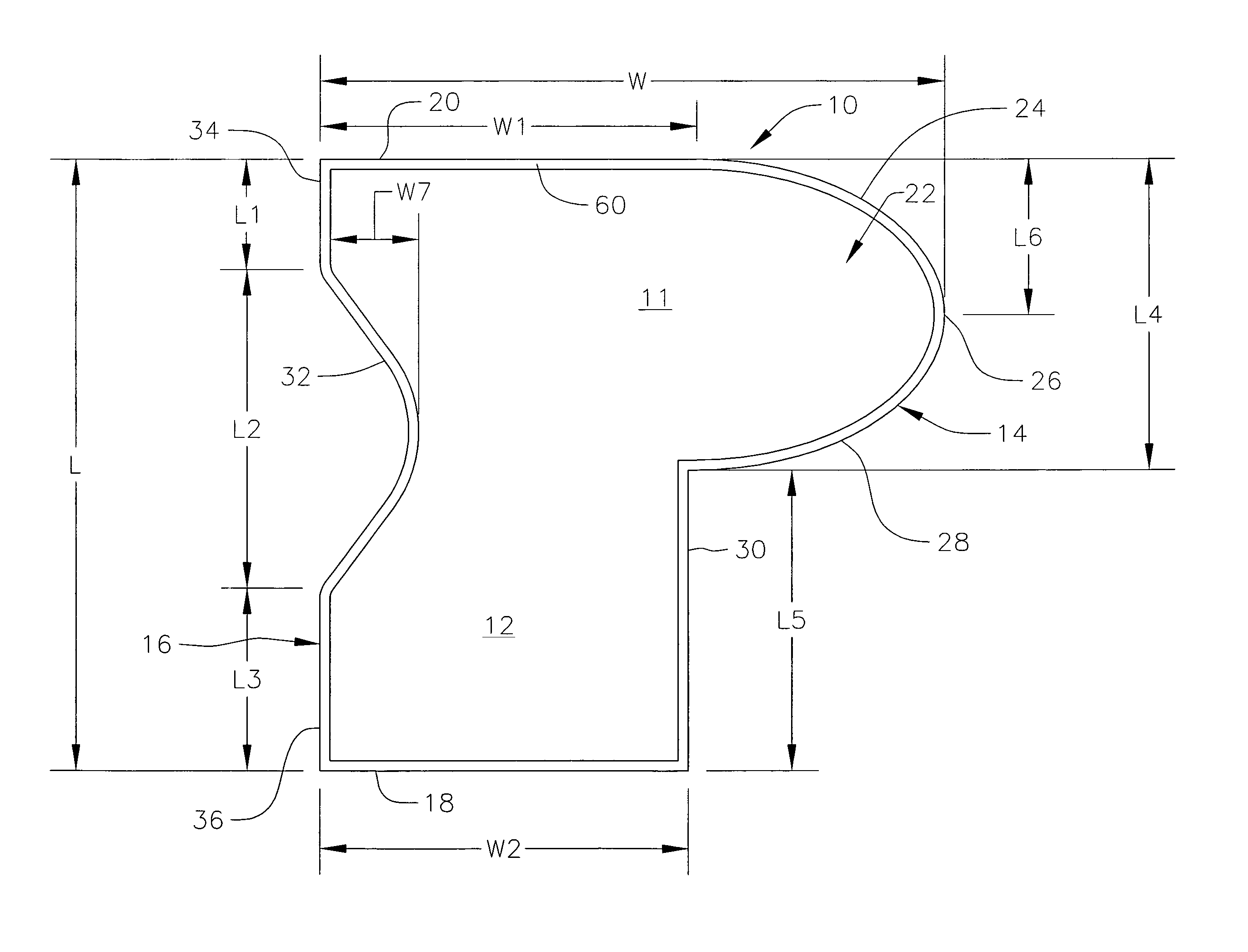
[0044]A two-level, L4-5, L5-S1 barrier as shown in FIG. 1 is described as follows:

[0045](1) The barrier structure is colored in light green or blue (or any other color other than red or yellow that will diminish the barrier from normal tissues) with a 2 mm border 60 of dark green or blue to identify the edges from the body of the barrier.

[0046](2) 0.1 to 5 mm thick depending on the material to be used for the barrier.

[0047](3) 9.5 to 10.5 cm high (dimension L) at its highest point with two widths.[0048](a) The upper section 11 has a width of 9-10 cm (dimension W) with a tapered tongue starting at 58-60 mm (dimension W1) from the left edge and ending with a height of 2 cm (dimension L6). This upper section is 4-5 cm high (dimension L4).[0049](b) The lower section is 58-60 mm wide (dimension W2) and 4-5 cm high (dimension L5).[0050](c) The upper width W1 and lower width W2 are approximately the same.

[0051](4) On the left margin a curved waist starts at 2 cm (dimension L1) from the upp...

example 2

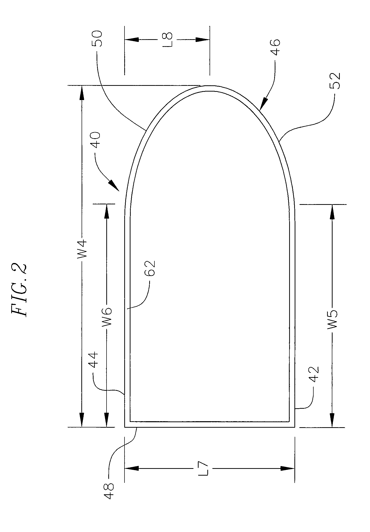
[0054]The single level and multiple level above L4-5 barrier as shown in FIG. 2 is described as follows:

[0055](1) The barrier structure is colored in light green or blue (or any other color other than red or yellow that will distinguish the barrier from normal tissues) with a 2 mm border 62 of dark green or blue to identify the edges from the body of the barrier.

[0056](2) 0.1 to 5 mm thick depending on the material to be used for the barrier.

[0057](3) 4 to 5 cm high or long (dimension L7) with a tapering right edge starting at 58 to 60 mm from the left edge (dimension W6) and ending at 9 to 10 cm from the right edge (dimension W4), with the taper down to 2 cm in height (dimension L8) at the left edge.

[0058](4) 9-10 cm wide (dimension W4) with the tapered edge 50 on the right.

[0059](5) The purpose of the right side extension as a tongue is to allow placement over the psoas muscle to act as an early identifier of the barrier upon re-operation.


PUM


Abstract

A flexible piece of barrier material for use in preventing or minimizing adhesions and fibrous attachments following anterior lumbar surgery. In one embodiment, the barrier structure comprises a multiple level device shaped as a generally wider tongue to function as a barrier at or above the L4-5 level, and a generally narrower lower section to function as a barrier at or below the L5-S1 level. The structure also can include a recessed waist section along an edge opposite the tongue to allow for easier placement in the L4-5 area. In another embodiment, a single level barrier for use at or above L4-5 is shaped as a tongue with a tapered outer extension to allow the barrier to extend laterally onto the psoas muscle to provide for identification of the barrier upon reoperation.

Description

CROSS-REFERENCE TO RELATED APPLICATION[0001]This application claims priority to Provisional Application No. 60 / 932,921, filed Jun. 4, 2007, incorporated herein by this reference.FIELD OF THE INVENTION[0002]This invention relates to an improved encasement prevention barrier for use in preventing or minimizing adhesions and fibrous attachments following anterior lumbar surgery.BACKGROUND[0003]Spine surgery, such as vertebral fusions, is common and is becoming more reliable as better methods are developed for stabilizing the back and improving bone grafts, for example, to repair disc injuries, vertebral fractures, and the effects of osteoarthritis. Many spine surgeries require an anterior approach, such as those for degenerative disc disease (both denovo and to correct failed prior back surgery), and for infected discs, tumor removal and scoliosis (e.g., for excision, drainage, or decompression).[0004]Anterior fusions are often preferable to posterior fusions because the bone surface a...

Claims


Application Information

Patent Timeline
Patent Type & Authority Patents(United States)
IPC IPC(8): A61B17/08A61F5/04A61B17/56
CPCA61F2/30721A61F2/442A61F2/4455A61F2002/009A61F2002/30688A61F2002/30932A61B17/56
Inventor BRAU, SALVADOR A.
Owner BRAU SALVADOR A
Why Eureka
Try Eureka