Multiple stage assembly assist fastener

a multi-stage, fastener technology, applied in the direction of threaded fasteners, screws, roofs, etc., can solve the problems of requiring several attempts and/or operators, affecting the performance of the panel, so as to achieve low installation force and high removal force , the effect of low manufacturing cos

Active Publication Date: 2006-08-08
NEWFREY
View PDF24 Cites 59 Cited by
  • Summary
  • Abstract
  • Description
  • Claims
  • Application Information

AI Technical Summary

Benefits of technology

[0009]A multiple stage assembly assist fastener of the present invention offers several advantages over conventional devices. The fastener of the present invention provides a relatively low installation force and a relatively high removal force. The fastener accommodates additional panel thickness due to foam or sound / vibration damping material. The fastener is inexpensive to manufacture, reliable and simple to install. Furthermore, the fastener of the present invention is particularly adapted for securing items to one another in a manner permitting a structure such as a panel to be temporarily mounted to a vehicle promoting a hands-free use of a fastener engagement tool to complete the panel installation. The features, functions, and advantages can be achieved independently in various embodiments of the present invention or may be combined in yet other embodiments.

Problems solved by technology

For panels such as instrument panels, the components and therefore the structure of the panel can have significant weight.
This procedure is time consuming and can often require several attempts and / or several operators.

Method used


Image

  • Multiple stage assembly assist fastener
  • Multiple stage assembly assist fastener
  • Multiple stage assembly assist fastener

Examples


Embodiment Construction

[0016]The following description of the preferred embodiment is merely exemplary in nature and is in no way intended to limit the invention, its application, or uses.

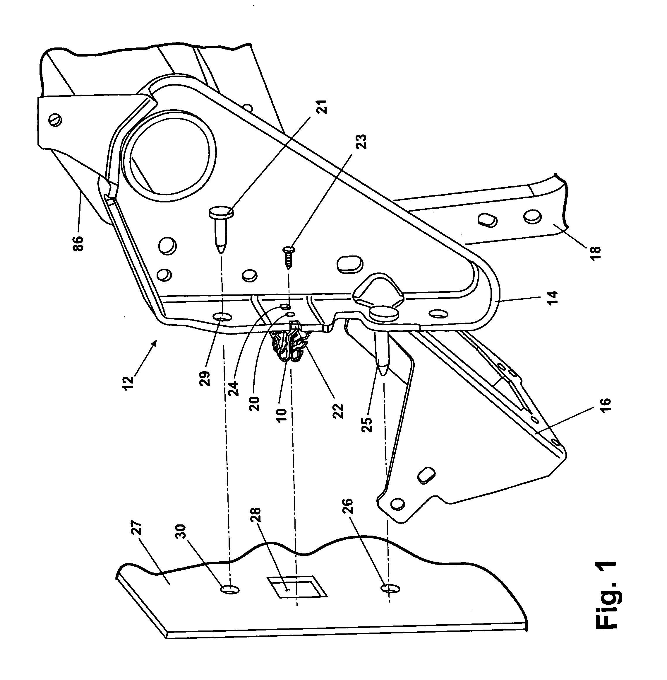
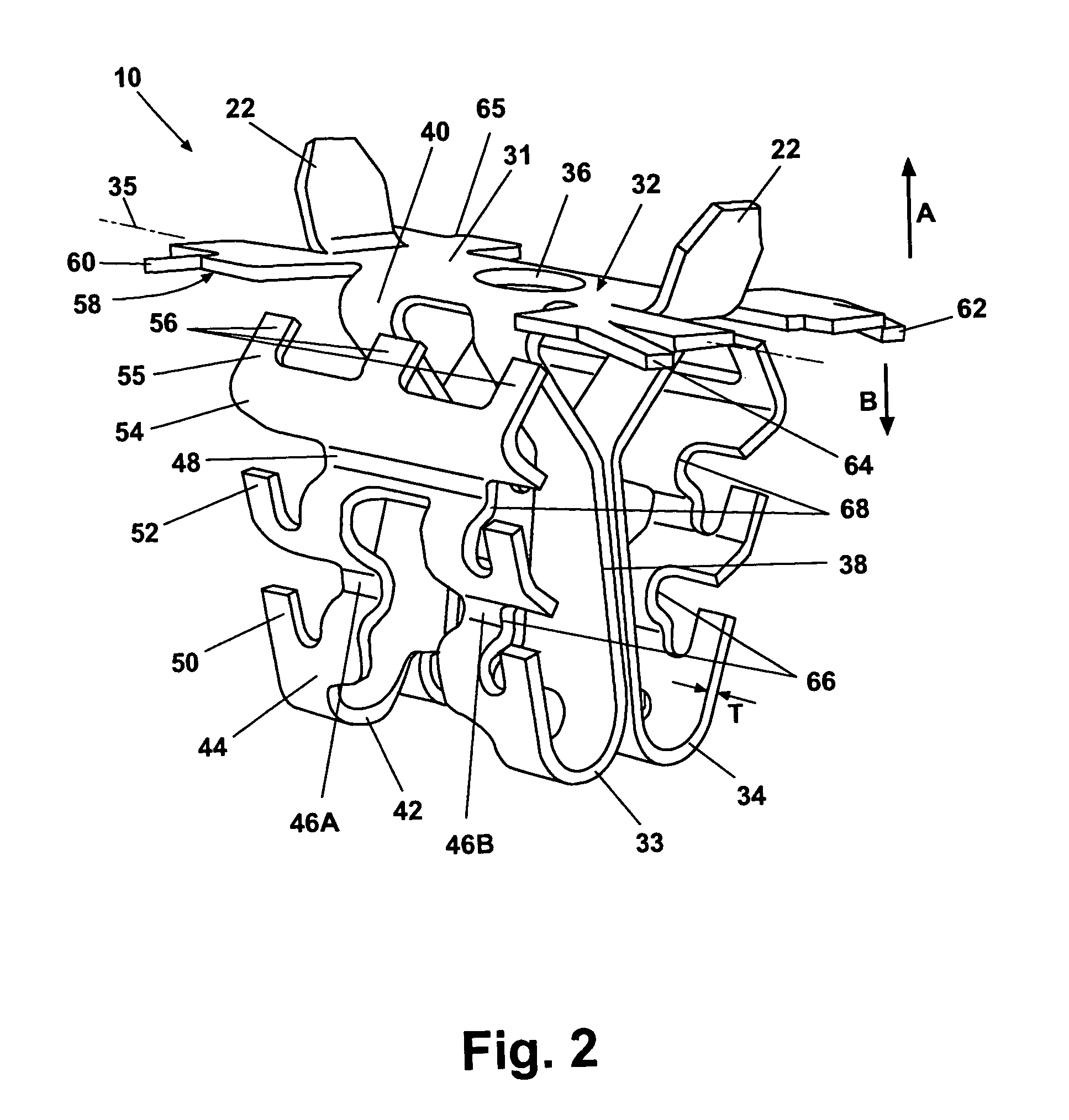
[0017]According to a preferred embodiment of the present invention and referring to FIG. 1, a resilient fastener 10 is connected to an installation assembly 12. Installation assembly 12 generally represents a structural configuration used to support, for example, an instrument panel, for installation in an automobile vehicle. Installation assembly 12 includes a plurality of metal mounting brackets 14, a plurality of metal support brackets 16, and one or more metal structural members 18. Resilient fastener 10 is attached to mounting bracket 14 adjacent a retainer mounting aperture 20 provided through mounting bracket 14. Retainer mounting aperture 20 is co-aligned with an engagement aperture 36 (described in greater detail with reference to FIG. 2) which together receive a mechanical fastener 23 preferably being a screw, ...


PUM


Abstract

A fastener joining an object to a panel includes a fastener plate nonrotatably receiving the object. Elastically displaceable elements, each having multiple concave shaped detents alternately engage a panel mounting aperture when the displaceable elements are inserted into the mounting aperture. Multiple retention positions are provided by the multiple detents.

Description

FIELD OF THE INVENTION[0001]The present invention relates generally to resilient clip fasteners and more particularly to a resilient clip fastener that employs a particular surface geometry to secure the body portion of the resilient clip to a structure.BACKGROUND OF THE INVENTION[0002]Many current vehicles employ resilient clips to secure various components to an automobile vehicle body. One such application concerns instrument panels that mount to the interior of the vehicle. Such panels provide one or more instruments together with instrument wiring harnesses or system connections.[0003]During assembly of the vehicle, it is a conventional procedure to install the entire panel assembly onto the interior of the vehicle in a single operation. In other words, the panel assembly is passed through either the windshield or backlight opening of the vehicle body on the assembly line and then the panel assembly is secured by line operators to the interior of the vehicle.[0004]In order to a...

Claims


Application Information

Patent Timeline
Patent Type & Authority Patents(United States)
IPC IPC(8): F16B5/06F16B2/24B60R13/01B60R13/02F16B19/00F16B37/04
CPCB60R13/0206F16B37/043B60R13/0256Y10T24/304Y10T24/307
Inventor SLOBODECKI, JEFFREY ASIUDYM, II, JACOB A
Owner NEWFREY
Why Eureka
Try Eureka