
Photoconductive drum and image forming apparatus having the same

a technology of image forming apparatus and drum, which is applied in the direction of electrographic process apparatus, instruments, corona discharge, etc., can solve the problems of degrading image quality, increasing repair and maintenance costs, and hand of the operator stained due to dirt on the surface, so as to achieve a higher pressing force and high pressing force

Inactive Publication Date: 2010-09-02
RICOH KK
View PDF4 Cites 39 Cited by
  • Summary
  • Abstract
  • Description
  • Claims
  • Application Information

AI Technical Summary

Benefits of technology

[0024]The present invention is made in light of the above problems and may provide a photoconductive drum where the end surface member is engaged with the photoconductive sleeve member, and the photoconductive drum is capable of not generating a higher pressing force when it is not necessary to apply the higher pressing force to the contacting section between the sleeve inner circumferential surface pressing member and the sleeve inner circumferential surface. Further, the photoconductive drum is capable of maintaining the engagement between the end surface member and the photoconductive sleeve member even when a high force is temporarily applied to the contacting section between the sleeve inner circumferential surface pressing member and the sleeve inner circumferential surface. Further, the present invention may provide an image forming apparatus having the above photoconductive drum.
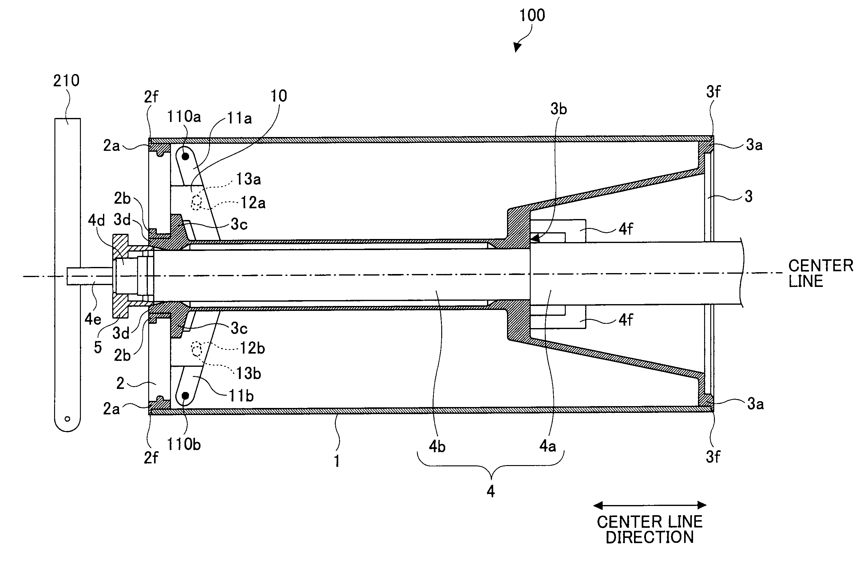
[0032]According to an embodiment of the present invention, even when a force is applied exceeding the maximum static friction force generated between the arm member 11 and the inner circumferential surface of the photoconductive sleeve member 1 upon the cap member 2 being engaged with the photoconductive sleeve member 1 due to the operation of the operation member 6 and the position of the cap member 2 with respect to the photoconductive sleeve member 1 is displaced outward in the center line direction, the displacement of the cap member 2 leads to increase the pressing force applied from the arm member 11 to the inner circumferential surface of the photoconductive sleeve member 1. Because of this feature, the larger the displacement becomes, the larger is the pressing force is applied to the contacting sections 112a and 112b where the arm members 11 are in contact with the inner circumferential surface of the photoconductive sleeve member 1. As a result, the engagement may be reinforced between the cap member 2 and the photoconductive sleeve member 1. Because of this feature, even when an extraordinary force is temporarily applied to the contacting sections 112a and 112b, the engagement may be maintained between the cap member 2 and the photoconductive sleeve member 1. On the other hand, as long as the position of the cap member 2 with respect to the photoconductive sleeve member 1 is not displaced outward in the center line direction, the pressing force applied to the contacting sections 112a and 112b where the arm members 11 are in contact with the inner circumferential surface of the photoconductive sleeve member 1 is equal to the pressing force applied when the cap member 2 is engaged with the photoconductive sleeve member 1 due to the operation of the operation member 6. Because of this feature, when the cap member 2 is engaged with the photoconductive sleeve member 1 and if no extraordinary pressing force is required to be applied to the contacting sections 112a and 112b where the arm members 11 are in contact with the inner circumferential surface of the photoconductive sleeve member 1, such extraordinary pressing force may not be applied to the contacting sections.

Problems solved by technology

However, in a case where the method of replacing the photoconductive sleeve member only is adopted, if an operator touches the surface of the used photoconductive sleeve member, the hand of the operator may be stained due to dirt on the surface.
Furthermore, if the operator touches the surface of a new photoconductive sleeve member to be used, the stain on the hand of the operator may be adhered to the surface of the photoconductive sleeve member and / or the surface of the photoconductive sleeve member may be damaged, thereby degrading the image quality.
Because of the restriction that the operator cannot touch the surface of the photoconductive sleeve member, in the apparatus in which only the photoconductive sleeve member is to be replaced, it may take longer to complete the replacement of the photoconductive drum, thereby increasing the repair and maintenance cost.
However, the operation of removing the handle member disposed in the photoconductive sleeve member 1 may be so difficult that it may increase time to complete the replacement of the photoconductive sleeve member 1.
However, from the viewpoint of saving resources, discarding the handle member in this method is a waste of resources.
As a result, it becomes possible to easily separate the handle member from the photoconductive sleeve member, and it may not increase time to complete the replacement of the photoconductive sleeve member.
Further, when, for example, an operator holds the other end surface member, and if the engagement is destroyed, the photoconductive sleeve member may be dropped off and the operator may be injured.
Because of this feature, it may become necessary to reinforce the members so as not to be deformed even when the higher pressing force is applied to the contacting section between the sleeve inner circumferential surface pressing member and the sleeve inner circumferential surface, thereby increasing the manufacturing costs.

Method used


Image

  • Photoconductive drum and image forming apparatus having the same
  • Photoconductive drum and image forming apparatus having the same
  • Photoconductive drum and image forming apparatus having the same

Examples


Embodiment Construction

[0057]In the following, embodiments of the present invention applied to a printer (hereinafter referred to as a printer 200) as an image forming apparatus will be described with reference to the accompanying drawings.

[0058]FIG. 4 schematically shows an exemplary configuration of the printer 200 according to an embodiment of the present invention. As shown in FIG. 4, the printer 200 includes a photoconductive drum 100 and a charging device 19, an exposure device 20, a development device 21, and a corona transfer device 43 which are arranged in the circumferential direction along the outer circumferential surface of the photoconductive drum 100, the corona transfer device 43 serving as transfer means.

[0059]After charges are uniformly distributed on the surface of the photoconductive drum 100 by the charging device 19, a laser light L in accordance with image data to be printed is irradiated onto the surface of the photoconductive drum 100 by the exposure device 20. By doing this, a st...


PUM


Abstract

A disclosed photoconductive drum includes a mechanism where, when the sleeve inner circumferential surface pressing member is in contact with the inner circumferential surface of the photoconductive sleeve member, a displacement of the first end surface member with respect to the photoconductive sleeve member in the center line direction leads to increasing a pressing force applied from the sleeve inner circumferential surface pressing member to the inner circumferential surface of the photoconductive sleeve member.

Description

CROSS-REFERENCE TO RELATED APPLICATIONS[0001]The present application claims priority under 35 U.S.C §119 to Japanese Patent Application No. 2009-047265 filed Feb. 27, 2009, the entire contents of which are hereby incorporated herein by reference.BACKGROUND OF THE INVENTION[0002]1. Field of the Invention[0003]The present invention generally relates to a photoconductive drum to be used in an electrophotographic image forming apparatus such as a copier, a printer, and a facsimile machine and an image forming apparatus having the photoconductive drum.[0004]2. Description of the Related Art[0005]A photoconductive drum having a cylindrical shape in an electrophotographic image forming apparatus is required to be replaced periodically because the surface of the photoconductive drum may be worn out and the electrical characteristics of the surface may be deteriorated in accordance with the number of printed pages and the like. Some types of photoconductive drums have a photoconductive sleev...

Claims


Application Information

Patent Timeline
IPC IPC(8): G03G15/00
CPCG03G15/751G03G21/1671G03G2221/1606
Inventor TAKAI, SHINGOTAKEUCHI, YOUICHISAITO, TOMOHIKO
Owner RICOH KK
Learn More