
Seat back for a vehicle seat comprising an integrated protective device

a protective device and seat back technology, applied in the direction of screws, chairs, threaded fasteners, etc., can solve the problems of inability to fully protect the head, so as to reduce the impact of the occupant's head, reduce the effect of installation space, and reduce the effect of internal acceleration

Inactive Publication Date: 2005-02-17
JOHNSON CONTROLS TECH CO
View PDF17 Cites 46 Cited by
  • Summary
  • Abstract
  • Description
  • Claims
  • Application Information

AI Technical Summary

Benefits of technology

[0013] According to the present invention, in particular because of the unlocking of the lever system, pivoting of the upper back part can preferably proceed so quickly that the upper back part is in the safety position before the onset of any head motion of the seat user resulting from the rear-end impact. In the safety position, the upper back part rests directly against the seat user's body so that the user, despite the acceleration acting on him or her due to the impact, advantageously can no longer freely move backward against the vehicle's direction of travel and incur accidental injuries.
[0015] It is advantageous to provide a force storage device or energy storage device as the torque-generating device for the pivoting motion of the cross member carrying the headrest. A preloaded torsion spring, in particular, has proven advantageous in this context, since it possesses a very low intrinsic acceleration and therefore requires less installation space for the same effect as compared to tension or compression springs.
[0016] The lever system of the immobilization means for retention of the upper back part in the normal use position can preferably comprise at least two coacting levers. A first lever (hereinafter called the pawl) can brace the pivotable crossmember, preloaded by the torsion spring, with respect to a stationary counterbearing; while a second lever (hereinafter called the immobilization lever) acts as immobilizer for the pawl. In the event of a rear-end impact, the immobilization lever is pivoted in such a way that it releases the immobilization of the pawl. Triggering of the immobilization lever can be effected with a very low actuation force, thereby making possible a very fast lever movement and thus rapid unlatching of the pawl.
[0020] It is particularly advantageous, in terms of reliably preventing a spring-back or bounce-back effect when the protective device takes effect, if the immobilization means for retention of the upper back part against a backward motion from the safety position into the normal use position (which means are also referred hereinafter to as the “recoil lock”) are embodied so that they make possible immobilization not only in the normal use position and in the safety position, but also in multiple positions located therebetween. This can be implemented, for example, by means of self-locking rolling-element or wedge-type locks that operate positively or nonpositively (preferably by jamming), or by means of a ratchet device. A suitable design of the recoil lock advantageously makes it possible to limit any recoil play of the upper back part (motion in the direction of the safety position) to a maximum angular magnitude of 1 degree.

Problems solved by technology

An undesirable effect, called the “whip effect,” occurs on the head and neck, resulting in hyperextension and overstressing of the cervical vertebrae and support muscles of the head.
It is disadvantageous in this context that the relative motion of the headrest does not occur until the occupant is thrown into the seatback.
Since the motion characteristics of the seat user cannot be accurately predicted in every case, however, in some circumstances the active counter-motion of the seatback or headrest may in fact cause incorrect, undesired, possibly dangerous effects.
For example, the impact of the occupant's head can in fact be further amplified, and occupant “ramping” (vertical movement in the seat) also cannot be prevented.
This generally results in failure of the seatback, which buckles due to overload and is no longer capable of supporting the occupant.
In particular, the seat user's head can end up at a height which is above the headrest, where it can no longer be supported.
A considerable residual accident risk thus exists with the known seatback.
Mechanisms that are triggered by displacement of the vehicle occupant's body into the seatback opposite to the direction of travel do not exhibit the desired protective effect.
The differing heights and therefore weights of vehicle users prove to be a particular disadvantage.
Because of this, it is impossible to ensure reliably that the triggering device of a protective device is correct and effective.
A further uncertainty factor is the delayed reaction of the previously disclosed mechanisms of this type.
This would in turn, however, result in an undesirable degradation of upholstery comfort.

Method used


Image

  • Seat back for a vehicle seat comprising an integrated protective device
  • Seat back for a vehicle seat comprising an integrated protective device
  • Seat back for a vehicle seat comprising an integrated protective device

Examples


Embodiment Construction

[0031] In the various Figures of the drawings, identical parts are always given the same reference characters, so that as a rule each is also described only once.

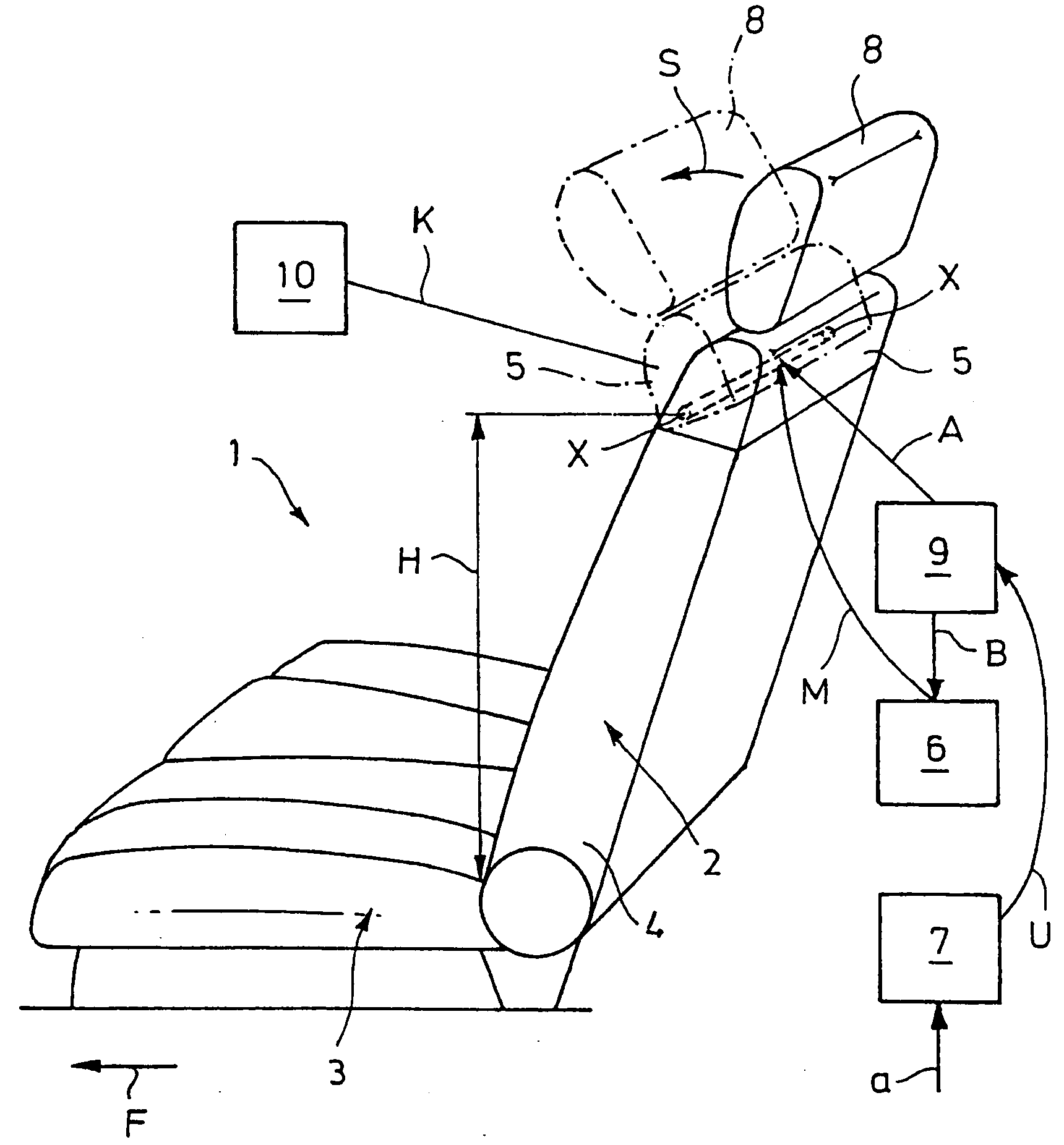
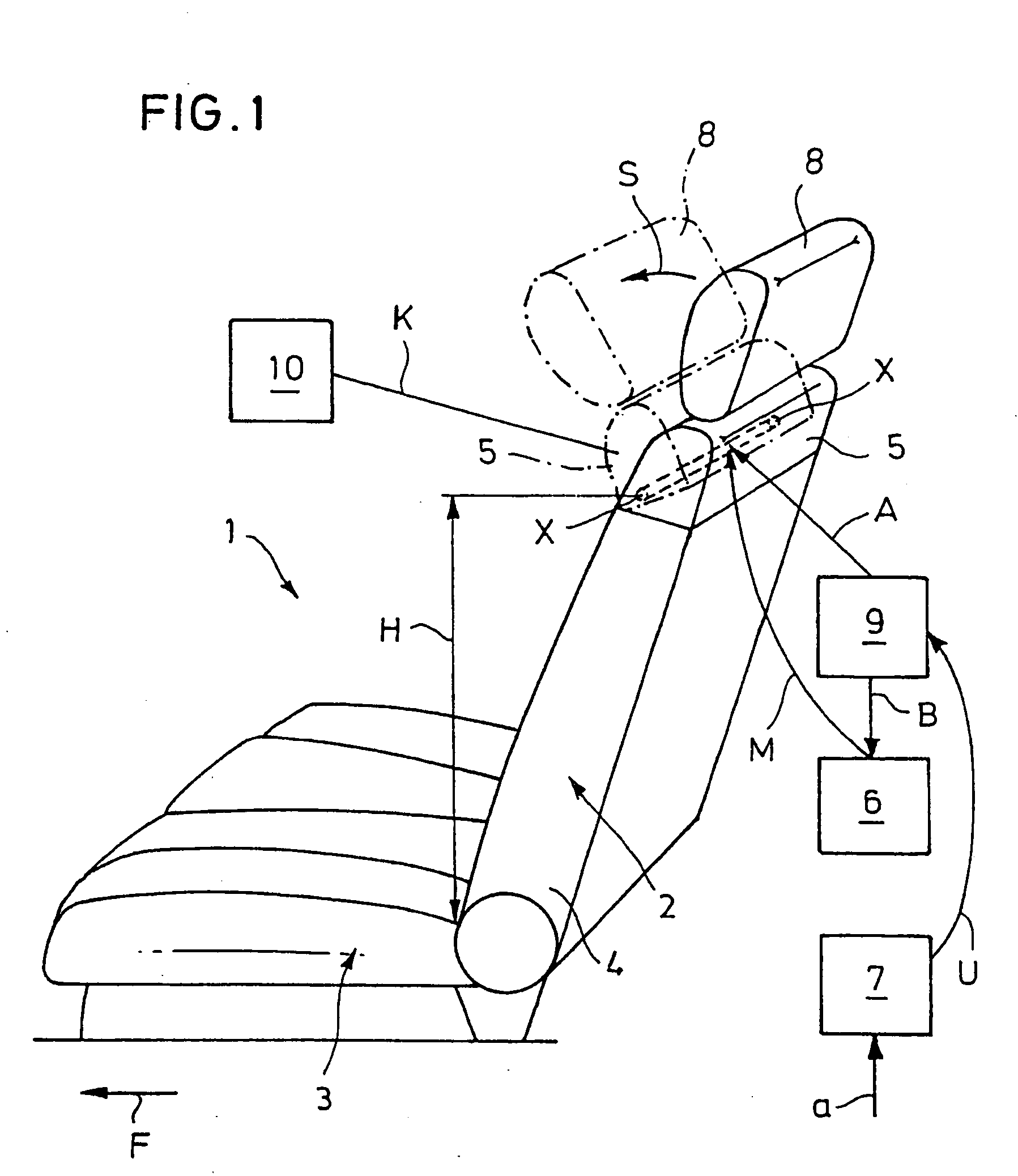
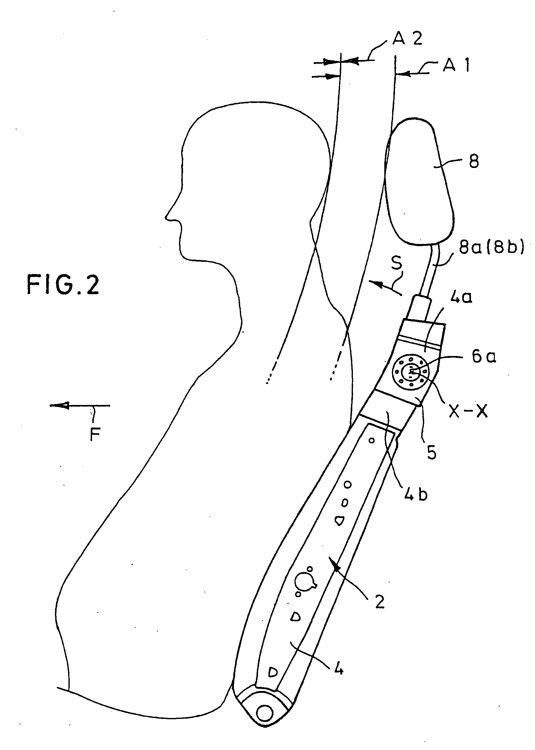
[0032] As is evident firstly from FIG. 1, a vehicle seat 1 comprises a seatback 2 according to the present invention and a seat part 3. Integrated into seatback 2 is a protective device that serves to protect the person in question against accident-related injuries, in particular cervical vertebra syndrome or acceleration trauma in the event of a rear-end impact. Seatback 2 has a lower back part 4 joined to seat part 3, and an upper back part 5 that is pivotable relative to lower back part 4 out of a normal use position (drawn with solid lines in FIG. 1), about an axis X-X extending in seatback 2 transversely to the longitudinal vehicle axis, through an angular range in a pivoting direction S pointing in direction of travel F into a safety position (drawn with dot-dash lines in FIG. 1), as a result of a torque acting in pi...


PUM


Abstract

The invention concerns a seatback for a vehicle seat, having an integrated protective device. The protective device includes a device that generates a torque acting in a pivoting direction on an upper back part, a rear-end impact detector that is-in effective connection with the torque-generating device in such a way that the device is activated in the event of the rear-end impact and the pivoting motion is initiated, and an immobilization device for retention of the upper back part in the normal use position.

Description

CROSS-REFERENCE TO RELATED PATENT APPLICATIONS [0001] This application is a divisional of U.S. application Ser. No. 10 / 049,698, which was the National Stage of International Application No. PCT / EP00 / 07995, filed Aug. 16, 2000, which claimed the benefit of German Application No. 199 38 904.7, filed Aug. 17, 1999, all of which are incorporated by reference.FIELD OF THE INVENTION [0002] The present invention concerns a seatback for a vehicle seat, having an integrated protective device against accident-related injuries in the event of a rear-end impact, in particular against cervical vertebra syndrome or acceleration trauma, having a lower back part joined to a seat part and having a upper back part that is pivotable relative to the lower back part out of a normal use position, about an axis extending in the seatback transversely to the longitudinal vehicle axis, through an angular range in a pivoting direction pointing in the direction of travel, as a result of a torque acting in the ...

Claims


Application Information

Patent Timeline
Patent Type & Authority Applications(United States)
IPC IPC(8): B60N2/48F16B39/282
CPCB60N2/4814B60N2/4847F16B39/282B60N2/4885B60N2/4852B60N2/888B60N2/815B60N2/853B60N2/847
Inventor HAKE, ERNST-JURGENMULLER, HANS-JOACHIMSCHMALE, GERHARDSTRIEDER, LUTZ
Owner JOHNSON CONTROLS TECH CO
Learn More