Electroacoustic miniature converter with retaining means for installation in a hearing device

a technology of electroacoustic miniature converter and holding frame, which is applied in the direction of deaf-aid sets, electric devices, etc., can solve the problems of further miniaturization

Inactive Publication Date: 2009-06-25
SIEMENS MEDICAL EQUIPMENT
View PDF2 Cites 9 Cited by
  • Summary
  • Abstract
  • Description
  • Claims
  • Application Information

AI Technical Summary

Benefits of technology

[0028]This is advantageous in that it is the...

Problems solved by technology

The relatively large space requirement, which prevents further m...

Method used


Image

  • Electroacoustic miniature converter with retaining means for installation in a hearing device
  • Electroacoustic miniature converter with retaining means for installation in a hearing device
  • Electroacoustic miniature converter with retaining means for installation in a hearing device

Examples


Embodiment Construction

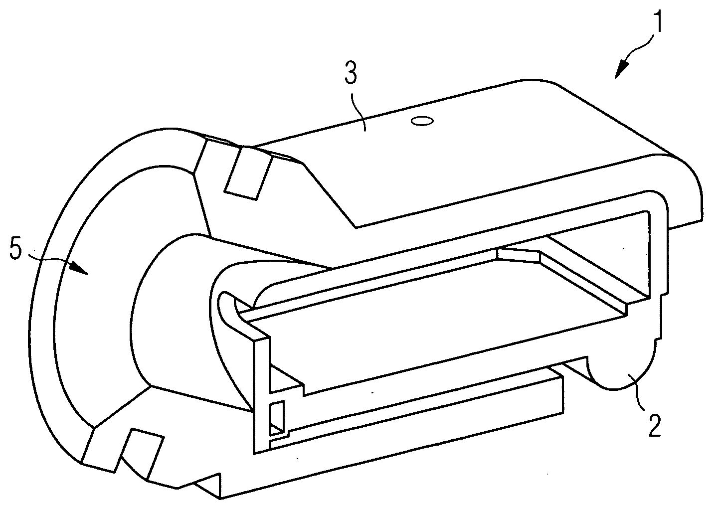
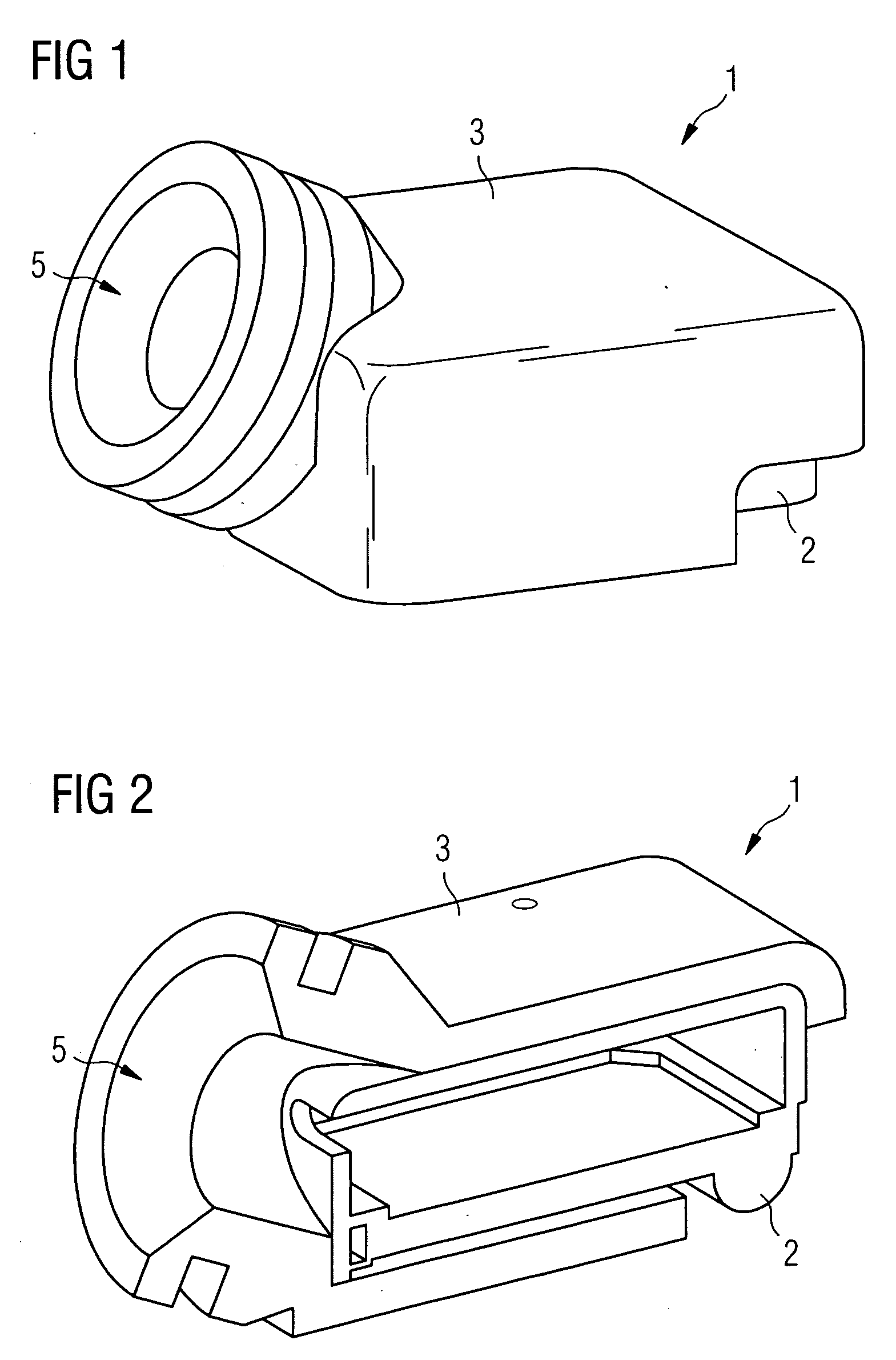
[0037]FIG. 1 shows a microphone 1 as one solution from the prior art, which includes an elastic retaining means 3 and a housing module 2 retained therein. With the opening 5 embodied in the retaining means 3 and the cylindrical collar formed therearound, the microphone can be elastically connected to a hearing device housing in a manner that inhibits structure-borne sound. The retaining means 3 almost completely surrounds the cuboid housing module 2.

[0038]FIG. 2 shows a perspective sectional view of the microphone 1 from FIG. 2. It is clear that the retaining means 3 almost completely surrounds the housing module 2. The final thickness of the retaining means 3 consequently increases the required installation volume by 30 to 50% as a result of this construction.

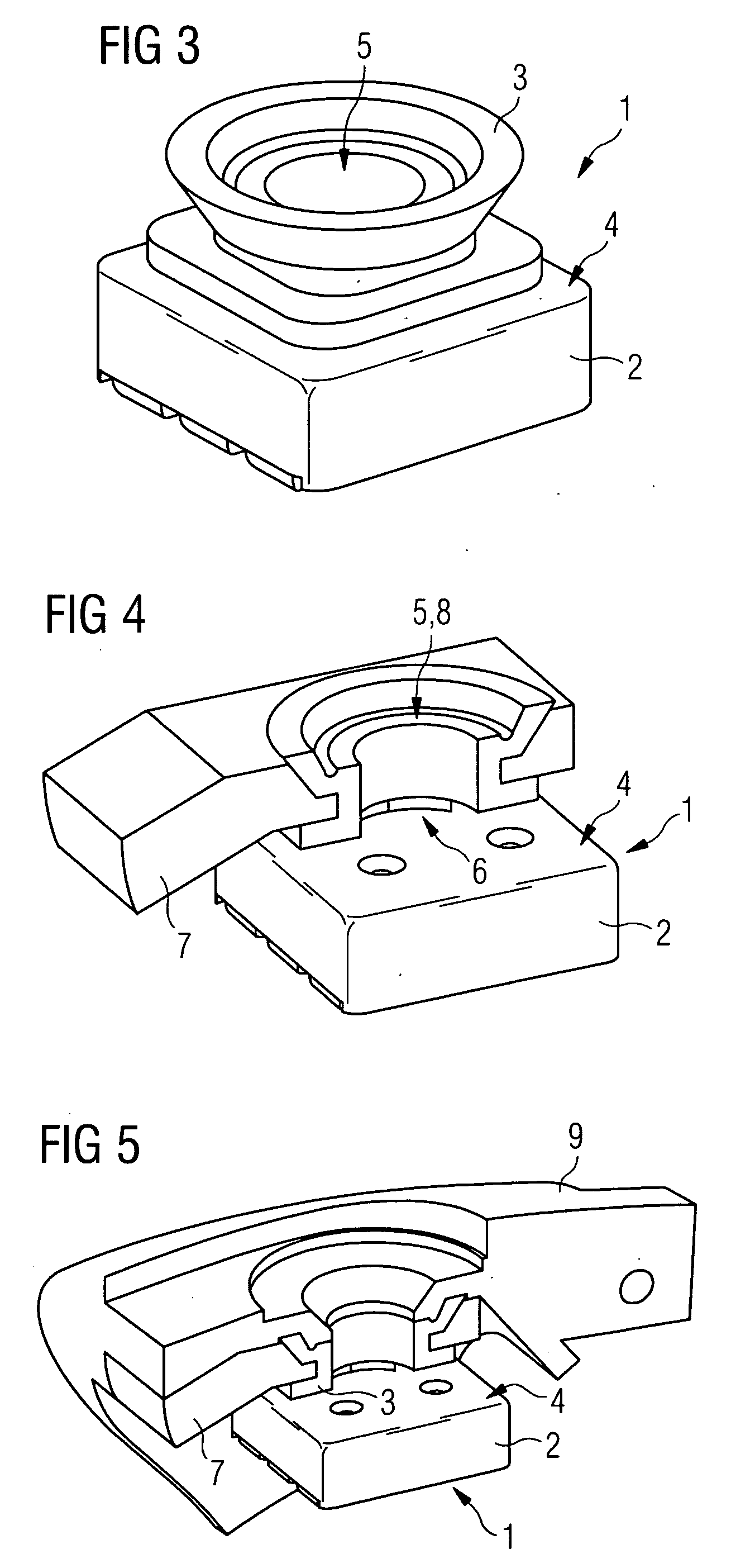
[0039]FIG. 3 shows a perspective view of an electroacoustic miniature converter 1, for instance a microphone. An elastic retaining means 3 is positioned on a polyhedral housing module 2, in which the electroacoustic components...


PUM


Abstract

An electroacoustic miniature converter for hearing devices is described. This includes a polyhedral housing module and an elastic retaining device, with the housing module and the retaining device being embodied such that the retaining device is connected to exclusively one single surface of the housing module.

Description

CROSS REFERENCE TO RELATED APPLICATIONS[0001]This application claims priority of German application No. 10 2007 061 310.7 DE filed Dec. 19, 2007, which is incorporated by reference herein in its entirety.FIELD OF INVENTION[0002]The invention relates to an electroacoustic miniature converter, a holding frame as and hearing devices.BACKGROUND OF INVENTION[0003]Electroacoustic miniature converters are used to convert acoustic signals into electrical signals and to convert electrical signals into acoustic signals. With numerous applications, like for instance hearing devices, an acoustic signal is recorded by an electroacoustic miniature converter (microphone) and processed, and an acoustic signal is output by an electroacoustic miniature converter (receiver, loudspeaker). To avoid feedback between the receiver and microphone, the output sound of the receiver must be prevented from being received by the microphone.[0004]With electroacoustic devices, in addition to the direct sound trans...

Claims


Application Information

Patent Timeline
IPC IPC(8): H04R25/00
CPCH04R25/604H04R25/456
Inventor FICKWEILER, WEMERTRAUTNER, MARKUSWEIDNER, TOM
Owner SIEMENS MEDICAL EQUIPMENT
Why Eureka
Try Eureka