Control device for a braking system of a vehicle, braking system, and method for operating a braking system for a vehicle

a control device and braking system technology, applied in the direction of braking systems, electric devices, instruments, etc., can solve the problems of functional impairment of the affected brake circuit, and achieve the effect of ensuring the implementationability of the booster control point, reducing the volume intake of the standard braking system, and reducing the amount of braking circuit damag

Active Publication Date: 2014-01-30
ROBERT BOSCH GMBH
View PDF16 Cites 8 Cited by
  • Summary
  • Abstract
  • Description
  • Claims
  • Application Information

AI Technical Summary

Benefits of technology

[0005]The present invention allows additional volume to be conveyed into the second brake circuit for the additional brake boosting, in particular in order to ensure the deceleration required by regulation, even in the event of a fault. For example, a defect in the first brake circuit during the establishment of the setpoint additional volume is recognized by comparing the at least one setpoint variable to the at least one actual variable, and additional brake boosting is subsequently activated in the second brake circuit. The functional impairment of the first brake circuit, in particular a circuit failure, may be compensated for in this way.
[0007]For a vehicle having the control device according to the present invention, the braking system equipped with same, and a vehicle operation using the corresponding method, the minimum vehicle deceleration required by regulation is easily ensured in error-free normal operation as well as in the event of a fault, in particular in the event of a failure of the front axle circuit. For example, in the event of a circuit failure the motor vehicle may bring about a vehicle deceleration of at least 2.44 m / s2. Thus, the driver may reliably and conveniently brake the vehicle, even after a functional impairment.
[0008]The main brake cylinder braking mode is understood to mean a mode / state of the second brake circuit in which the second brake circuit is connected to the main brake cylinder in such a way that the driver is still able to brake the at least one second wheel brake cylinder via a pressure buildup in the main brake cylinder. Thus, in one embodiment of the present invention it is not necessary to close a shutoff valve between the main brake cylinder and the second brake circuit prior to transferring the actual additional volume. Instead, the present invention may also be carried out when this type of shutoff valve is present in an at least partially opened state, in particular in the opened state. In the present invention, the driver still has direct access to the second brake circuit. The driver may thus control / actively adjust the brake pressure that is present in the at least one second wheel brake cylinder after or during the transfer of the actual additional volume. In other words, via the applied pedal travel / pedal pressure and the applied counterforce the driver may regulate the pressure in the second (intact) brake circuit with respect to the increased counterpressure from the at least one volume conveying device, such as a pump and / or a plunger.
[0009]It is pointed out here that the present invention provides for a transfer of an additional brake fluid volume into the second brake circuit, which is hydraulically connected to the main brake cylinder and in which braking may still be carried out via the main brake cylinder, while in the conventional method a brake pressure is actively set by regulation in an intact brake circuit with a closed shutoff valve. Thus, in contrast to the regulation with the shutoff valve closed, the driver may quickly change the brake pressure which has built up in the at least one second wheel brake cylinder, without the need for a complicated or expensive electronics system.
[0011]While the conventional method results in a by-wire brake circuit in which a pressure reduction is possible only by regulation via the continuously adjustable valve, in the present invention it is not necessary to actively regulate the pressure in the second (remaining intact) brake circuit above the pressure level generated by the driver, based on the estimated braking input. Thus, an electronics system which is less expensive and which requires less installation space is also applicable for the implementability of the present invention.

Problems solved by technology

This may result in a functional impairment of the affected brake circuits.

Method used


Image

  • Control device for a braking system of a vehicle, braking system, and method for operating a braking system for a vehicle
  • Control device for a braking system of a vehicle, braking system, and method for operating a braking system for a vehicle
  • Control device for a braking system of a vehicle, braking system, and method for operating a braking system for a vehicle

Examples


Embodiment Construction

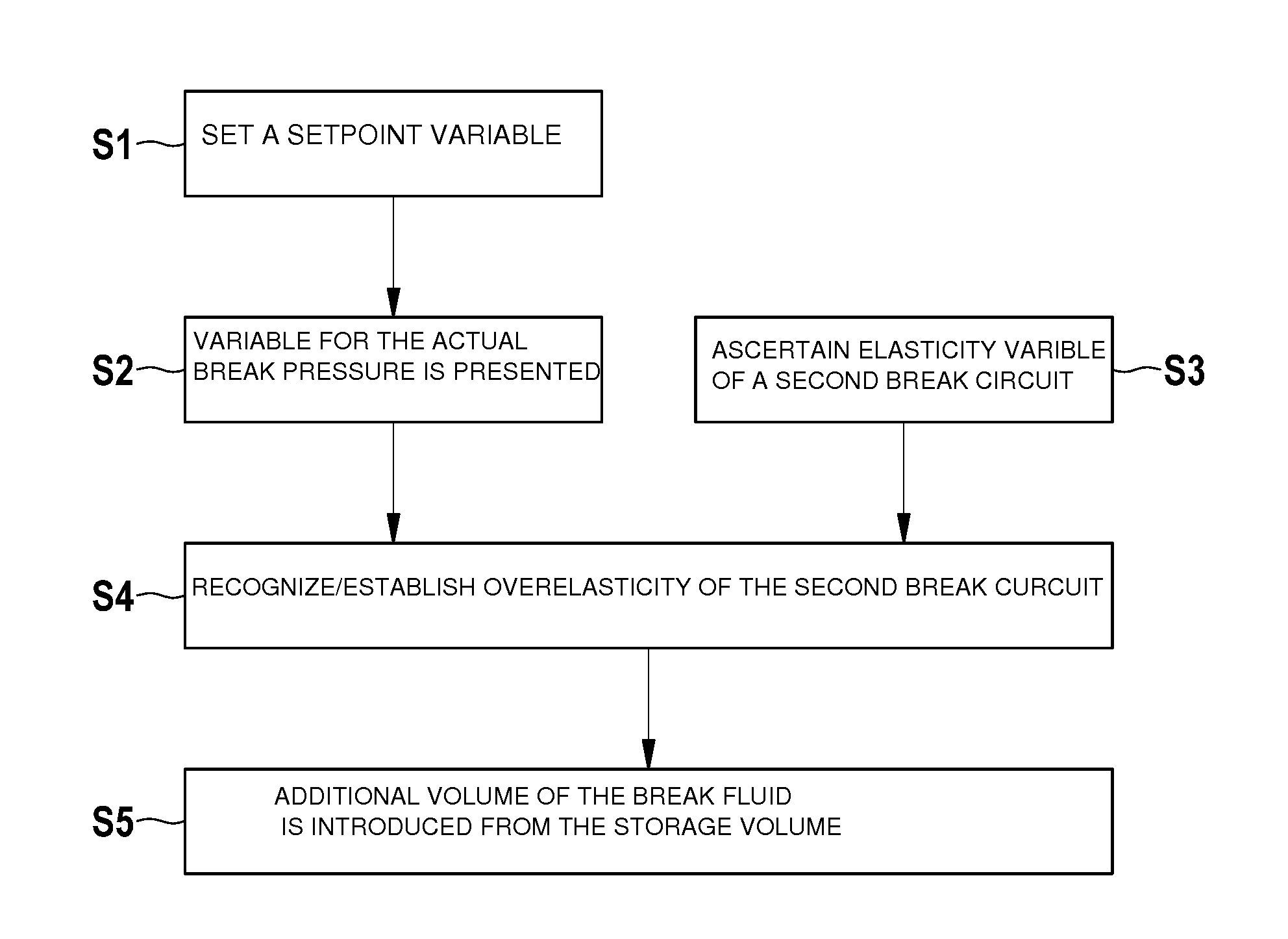
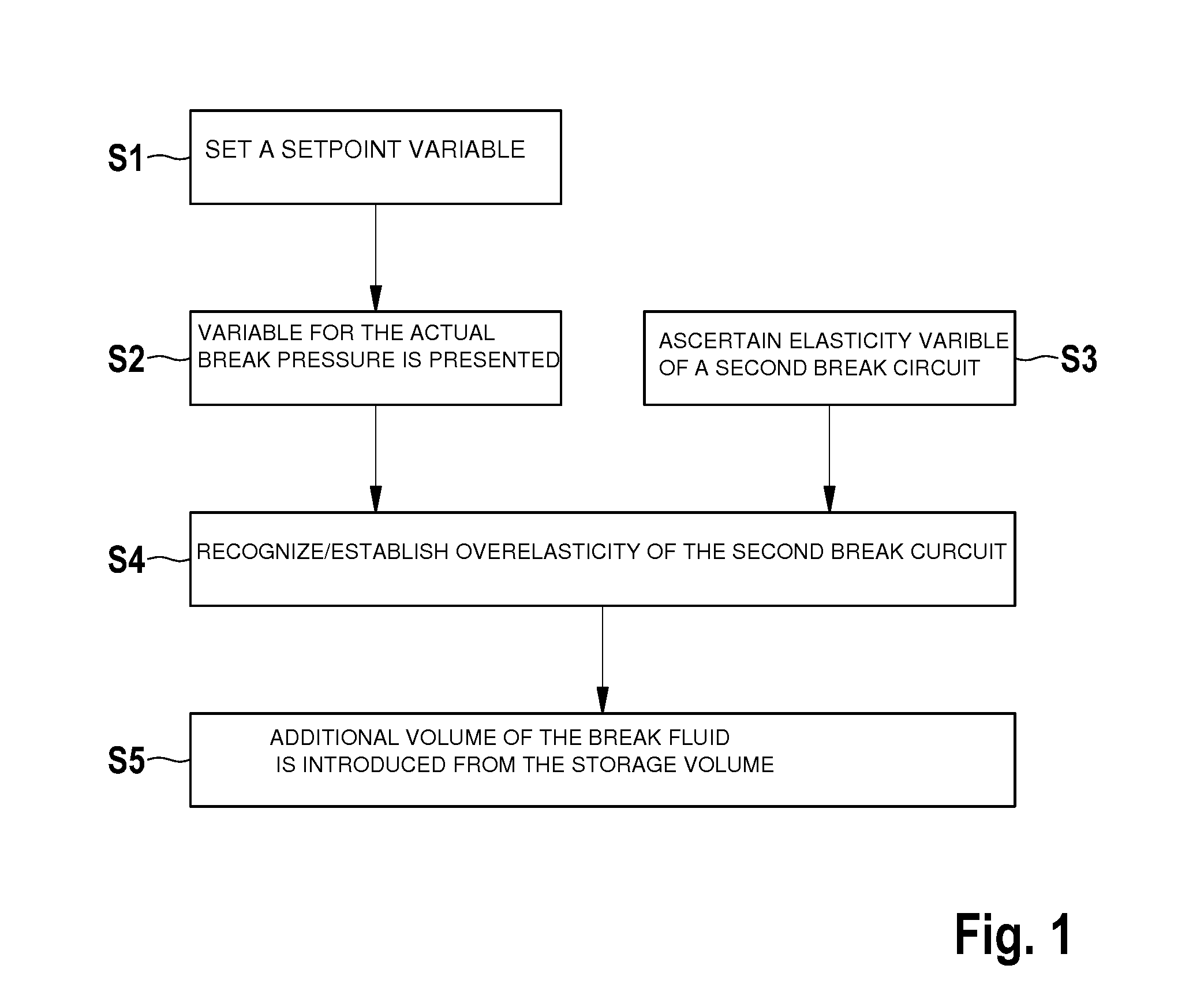
[0016]FIG. 1 shows a flow chart for explaining a first specific embodiment of the method for operating a braking system.

[0017]The method described below may be carried out using a braking system which includes a main brake cylinder, a storage volume, external to the brake circuit, which is fillable with a brake fluid, a first brake circuit having at least one first wheel brake cylinder, a second brake circuit having at least one second wheel brake cylinder, and at least one volume conveying device. The at least one volume conveying device may be a pump and / or a plunger, for example.

[0018]The at least one second brake circuit is operable at least in a main brake cylinder braking mode in which a pressure in the second brake circuit is controllable with the aid of the main brake cylinder. This may be understood to mean that the driver has the option of braking the second brake circuit which is in the main brake cylinder braking mode by activating a brake activation element, for example...


PUM


Abstract

A control device for a braking system of a vehicle, with the aid of which at least one provided setpoint variable regarding a setpoint brake pressure to be set in a first brake circuit and at least one provided actual variable regarding an actual brake pressure that is present in the first brake circuit, and / or an elasticity variable regarding an elasticity of a second brake circuit of the braking system are receivable, and a default variable regarding a setpoint additional volume of a brake fluid of the second brake circuit which is in a main cylinder braking mode is establishable, by taking into account a first deviation variable of the at least one actual variable from the at least one setpoint variable, and / or a second deviation variable of the elasticity variable from a predefined setpoint elasticity variable, so that a control signal corresponding to the established default variable is outputtable to at least one volume conveying device. Moreover, also described is a method for operating a braking system for a vehicle.

Description

FIELD OF THE INVENTION[0001]The present invention relates to a control device for a braking system of a vehicle and a braking system having this type of control device. Moreover, the present invention relates to a method for operating a braking system for a vehicle.BACKGROUND INFORMATION[0002]Braking systems for motor vehicles having two independent (separate) hydraulic brake circuits are known from the related art. Due to the independent design of the two brake circuits, in the event of a circuit failure due to a brake circuit defect it should still be possible to ensure at least minimum functioning of the braking system, and thus prevent a total failure of the braking system.[0003]A method for ascertaining a malfunction of a pressure sensor or a brake circuit of a hydraulic vehicle braking system having two brake circuits is described in German Published Patent Application No. 102 24 590, for example. The malfunction or the failure is recognizable by comparing a hydraulic pressure...

Claims


Application Information

Patent Timeline
Patent Type & Authority Applications(United States)
IPC IPC(8): B60T8/17
CPCB60L3/0023B60L7/18B60L7/26B60L2240/12B60L2240/461B60T7/042B60T8/17B60T8/4872B60T8/885B60T13/662B60T13/686B60T2270/402B60T2270/403B60T8/4072B60L7/24B60T8/171B60T8/26B60T8/32B60T11/10B60T13/10B60T13/12
Inventor STRENGERT, STEFANDROTLEFF, DIRKKOTITSCHKE, MICHAEL
Owner ROBERT BOSCH GMBH
Why Eureka
Try Eureka