
Electric power tool

a technology of electric power tools and power tools, which is applied in the direction of portable power tools, dynamo-electric machines, electrical apparatus, etc., can solve the problems of deterioration of usability of electric power tools and impaired functions of electric power tools

Inactive Publication Date: 2014-04-03
MAKITA CORP
View PDF4 Cites 9 Cited by
  • Summary
  • Abstract
  • Description
  • Claims
  • Application Information

AI Technical Summary

Benefits of technology

The patent text discusses how to make electric power tools smaller without compromising their effectiveness. By reducing the size of the housing that surrounds the tool, while keeping the size of the motor and rotational drive force constant, the tool can still perform its tasks effectively. This allows for a smaller, yet still effective, electric power tool.

Problems solved by technology

For this reason, the function of the electric power tool may be impaired.
However, when the locations of screws used in the “combining screwing” are positioned offset outwardly as compared to the locations of screws used in the “attaching screwing”, spaces used in the “combining screwing” protrude outwardly in the lateral direction, and thus usability of the electric power tool may deteriorate.

Method used


Image

  • Electric power tool
  • Electric power tool
  • Electric power tool

Examples


Embodiment Construction

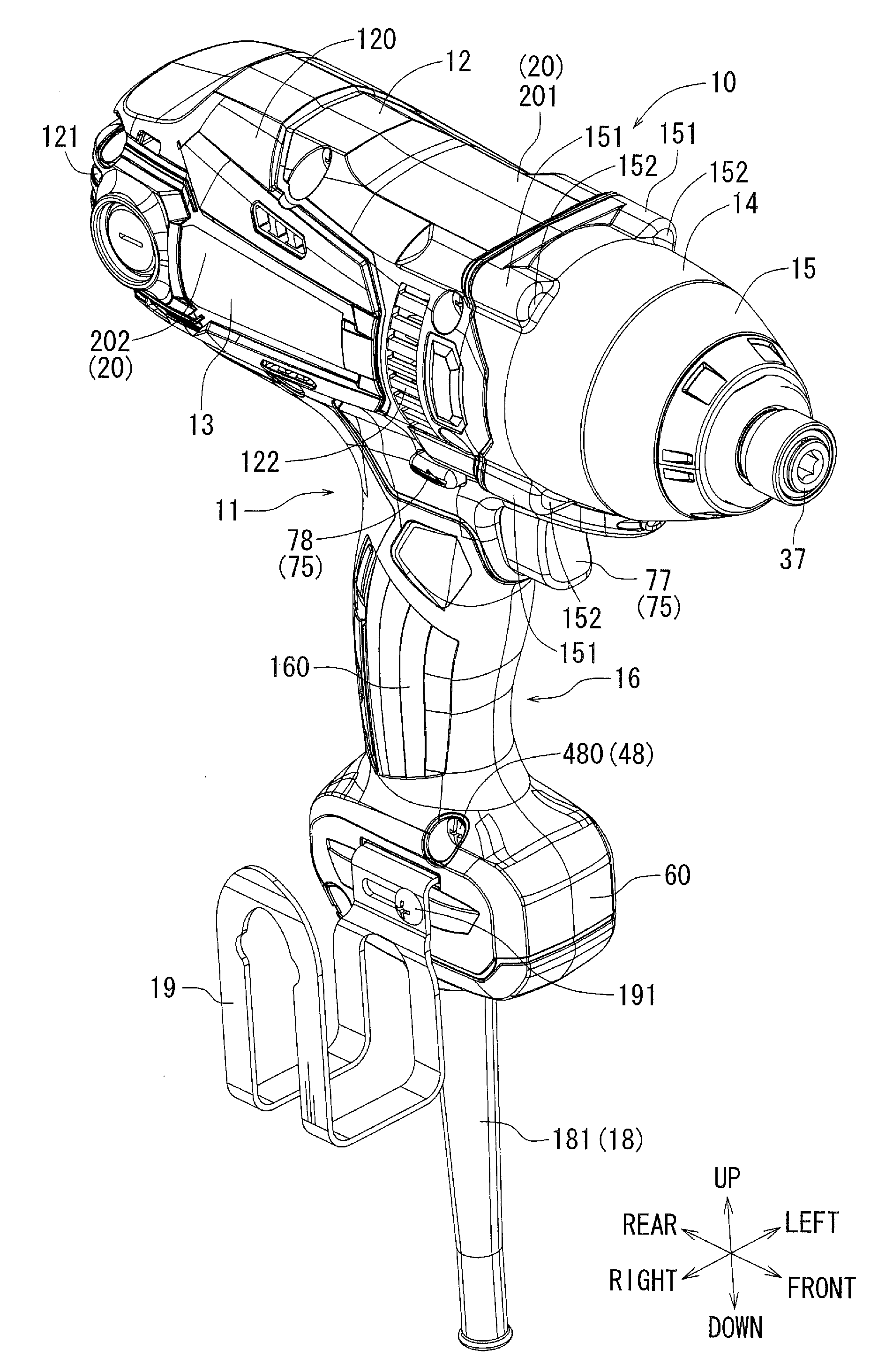
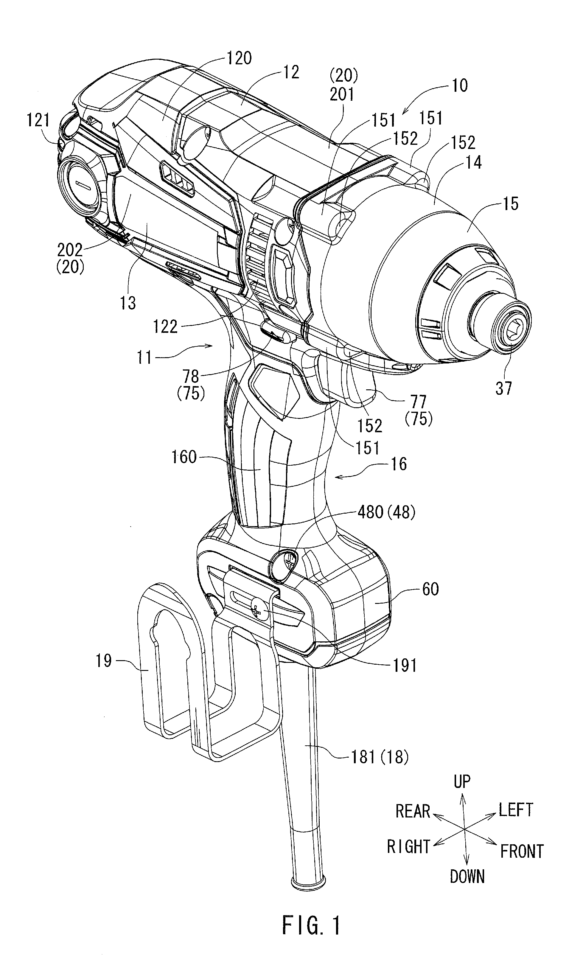
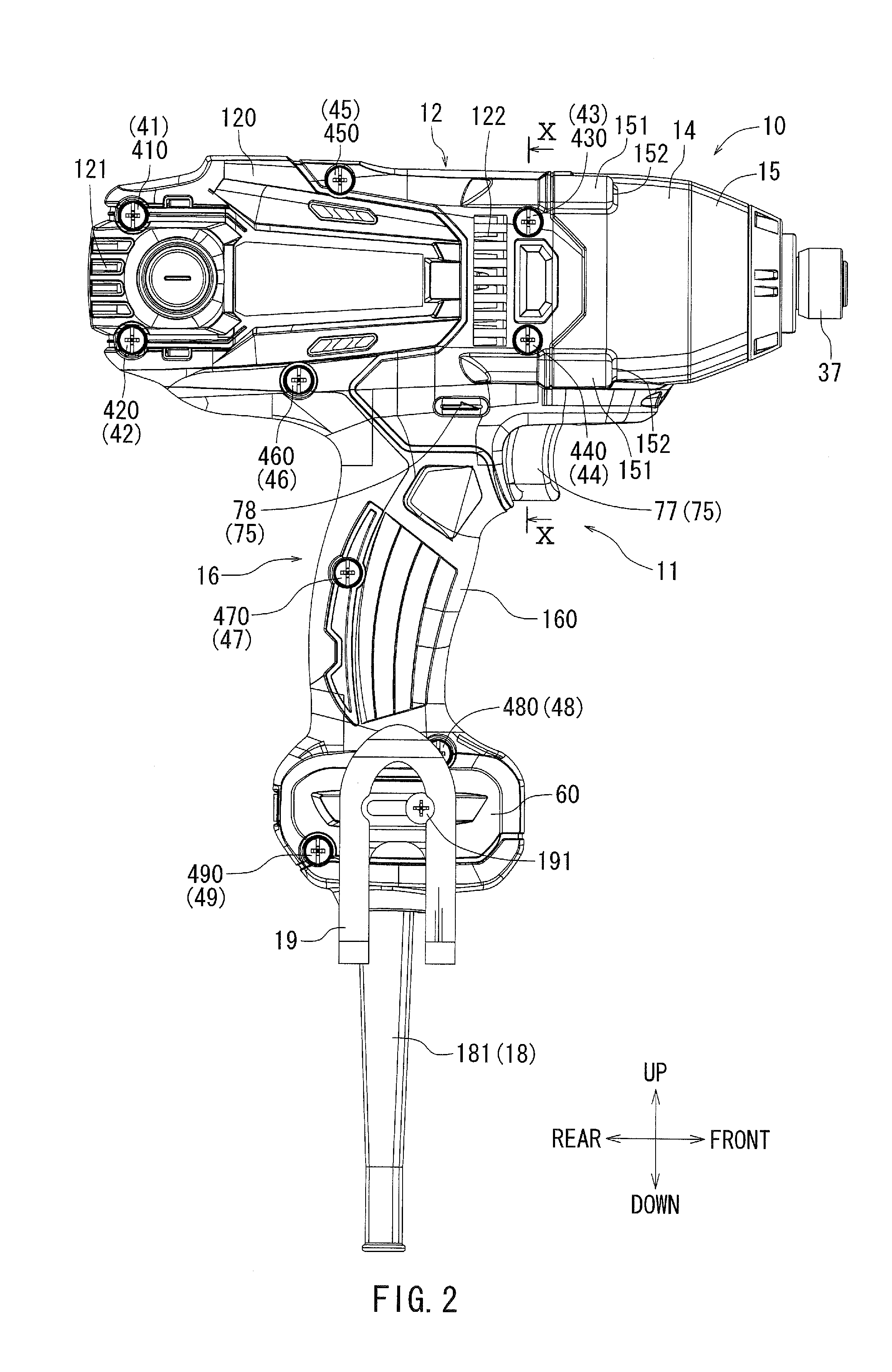
[0034]Each of the additional features and teachings disclosed above and below may be utilized separately or in conjunction with other features and teachings to provide an electric power tool. Representative examples of the present teaching, which examples utilize many of these additional features and teachings both separately and in conjunction with one another, will now be described in detail with reference to the attached drawings. This detailed description is merely intended to teach a person of skill in the art further details for practicing preferred aspects of the present teachings and is not intended to limit the scope of the invention. Only the claims define the scope of the claimed invention. Therefore, combinations of features and steps disclosed in the following detailed description may not be necessary to practice the invention in the broadest sense, and are instead taught merely to particularly describe representative examples of the invention. Moreover, various feature...


PUM


Abstract

In an electric power tool in which an electric motor is mounted in a housing that has a half-split structure, positions of middle screw fastening portions when a left housing and a right housing are fixed to each other by screws are located between a front protruding coil portion and a rear protruding coil portion. In other words, the protruding coil portions are located on either the front side or the rear side of the position of middle screw fastening portions when the left and right housings are fixed to each other by the screws. Accordingly, it is possible to effectively utilize a dead space that is likely to be formed between the front protruding coil portion and the rear protruding coil portion.

Description

[0001]This application claims priority to Japanese patent application serial number 2012-220555 and Japanese patent application serial number 2012-220556, the contents of which are incorporated herein by reference.BACKGROUND OF THE INVENTION[0002]1. Field of the Invention[0003]The present invention relates to an electric power tool in which an electric motor is mounted in a housing that has a half-split structure.[0004]2. Description of the Related Art[0005]In an electric power tool, a drive motor is mounted in a housing that forms an outer covering (for example, refer to Japanese Laid-Open Patent Publication No. 2012-011533). The housing is formed by combining and integrating half-split resin-molded members. The half-split resin-molded members are combined with each other by screwing, to form the integrated housing (hereinafter, this screwing is termed “combining screwing”). The direction in which screws are located corresponds to a direction in which the half-split resin molded me...

Claims


Application Information

Patent Timeline
IPC IPC(8): H02K7/14
CPCH02K7/145B25F5/02
Inventor KUMAGAI, RYUNOSUKE
Owner MAKITA CORP
Learn More