Load driving apparatus

a technology of load driving and load, applied in the direction of instruments, light sources, electroluminescent light sources, etc., can solve problems such as lowering efficiency, and achieve the effect of high power consumption efficiency

Inactive Publication Date: 2012-04-17
PANASONIC CORP
View PDF9 Cites 5 Cited by
  • Summary
  • Abstract
  • Description
  • Claims
  • Application Information

AI Technical Summary

Benefits of technology

[0007]Accordingly, the present invention is intended to solve the above-mentioned problem, and an object of the present invention is to provide a load driving apparatus for driving a load, capable of achieving high efficiency in power consumption over a wide variation range of a load current.
[0008]For the purpose of achieving the above-mentioned object, a load driving apparatus according to the present invention has a load current setting signal generating section operable to generate a desired load current setting signal; a load current generating section operable to generate a load current based on the load current setting signal to drive a load; a reference voltage generating section operable to generate a reference voltage based on the load current setting signal; and a drive voltage generating section operable to generate a drive voltage, to supply the drive voltage to the load, to generate a between-both-terminals voltage between both terminals of the load current generating section based on the drive voltage and to control the drive voltage so that the difference between the between-both-terminals voltage and the reference voltage becomes small.
[0009]Since the load driving apparatus according to the present invention changes the reference voltage depending on the load current required to drive a load, the load driving apparatus can drive the load with a minimum power loss over wide ranges of load conditions.

Problems solved by technology

In other words, the conventional configuration described above has a problem of lowering efficiency when the load is light.

Method used


Image

  • Load driving apparatus
  • Load driving apparatus
  • Load driving apparatus

Examples


embodiment 1

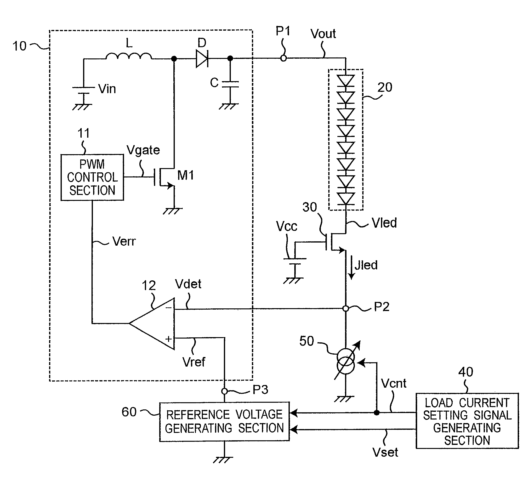
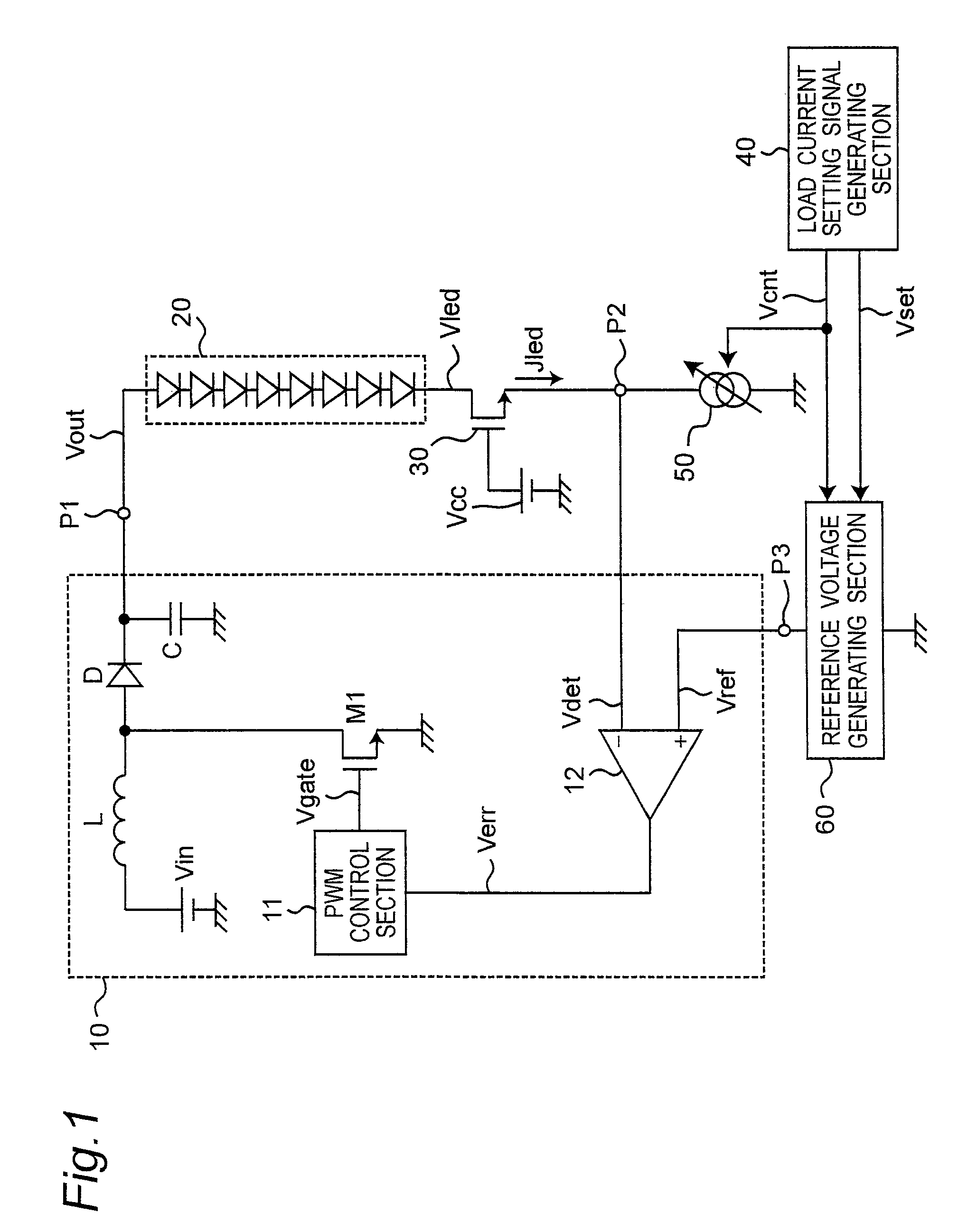
[0016]A load driving apparatus according to Embodiment 1 will be described below referring to FIGS. 1 and 2. FIG. 1 is a block diagram showing an overall configuration example of this load driving apparatus according to Embodiment 1. As shown in FIG. 1, the load driving apparatus includes a drive voltage generating section 10, a high withstand voltage MOSFET (metal-oxide semiconductor field effect transistor) 30, a load current setting signal generating section 40, a load current generating section (also referred to as a constant current circuit) 50 and a reference voltage generating section 60, and drives a load 20. The high withstand voltage MOSFET 30 is also referred to as a voltage buffer section.

[0017]The load 20 is formed of an LED array including multiple LEDs (light emitting diodes) connected in series, and light is emitted by passing a predetermined load current Jled through the LED array. The anode terminal of the LED array (the load 20) is connected to the output terminal...

embodiment 2

[0045]In the following description of Embodiment 2, differences from Embodiment 1 will be mainly described. Since the configurations, operations and effects other than those relating to the differences are similar to those according to Embodiment 1, their descriptions are omitted.

[0046]FIG. 4 is a block diagram showing an overall configuration example of a load driving apparatus according to Embodiment 2. In this load driving apparatus, a series circuit formed of a load 21, a high withstand voltage MOSFET 31 and a load current generating section 51 is connected in parallel with the series circuit formed of the load 20, the high withstand voltage MOSFET 30 and the load current generating section 50. In addition, a drive voltage generating section 10A is equipped with an error amplifier 12A having a configuration partly different from that of the error amplifier 12 according to Embodiment 1.

[0047]The load current generating section 51 supplies a load current Jled2 based on the load cu...


PUM


Abstract

The load driving apparatus according to the present invention includes a load current setting signal generating section, a load current generating section, a reference voltage generating section and a drive voltage generating section. The load current setting signal generating section generates a desired load current setting signal. The load current generating section generates a load current based on the load current setting signal to drive the load. The reference voltage generating section generates a reference voltage based on the load current setting signal. The drive voltage generating section generates a drive voltage, supplies the drive voltage to the load, generates a between-both-terminals voltage between both terminals of the load current generating section based on the drive voltage and controls the drive voltage so that the difference between the between-both-terminals voltage and the reference voltage becomes small.

Description

BACKGROUND OF THE INVENTION[0001]1. Field of Invention[0002]The present invention relates to a load driving apparatus for driving a load, and more particularly, to a load driving apparatus for driving a load, such as LEDs (light emitting diodes), connected to a power source circuit with a constant current.[0003]2. Description of Related Art[0004]In recent years, LEDs for the backlights of LCDs (liquid crystal displays) are being widespread as one of uses of LEDs. Generally speaking, when LEDs are used for the backlight of an LCD, a predetermined current is passed through multiple LEDs connected in series, whereby light can be emitted. At this time, the number of the LEDs and the amount of the current are determined depending on the amount of light required. Furthermore, a drive voltage for driving the LEDs is generated using a voltage conversion circuit for converting a power source voltage into a predetermined voltage. This voltage conversion circuit detects and feeds back the volt...

Claims


Application Information

Patent Timeline
Patent Type & Authority Patents(United States)
IPC IPC(8): H05B37/00
CPCH05B33/0815H05B33/0824H05B45/3725H05B45/44
Inventor TAKATA, GOKATAOKA, SHINICHIROYAMAMOTO, YASUNORIKAWAHARA, TSUKASAUEDA, RYUJIITOU, DAISUKE
Owner PANASONIC CORP
Why Eureka
Try Eureka