LED string driver with shift register and level shifter

a technology of shift register and led string, which is applied in the direction of process and machine control, instruments, lighting and heating apparatus, etc., can solve the problems of inability to compensate for the dark time, low utilization of individual leds, and current limit means, etc., and achieves cost-effective and scalable effects

Active Publication Date: 2012-04-17
SIGNIFY HLDG BV
View PDF11 Cites 6 Cited by
  • Summary
  • Abstract
  • Description
  • Claims
  • Application Information

AI Technical Summary

Benefits of technology

[0007]With respect to the second possibility, it is an object of the present invention to provide a device which overcomes the above-mentioned problem and which is simple, cost-effective and scalable.
[0014]The inventive device allows to control OLED / LED elements of a string separately, e.g. switching the elements on and off. This feature enables the use of pixelated LED lamps without drawbacks with respect to efficiency. As mentioned, the inventive device includes three essential features, namely a serial-to-parallel converter to connect a string to a simple serial data source, the level shifting features which are required to drive a series connection of OLEDs / LEDs, and the shunting switch.
[0017]In a preferred embodiment, said shunting switches are switched on when said switch controller means are programmed by a serial data stream. In a preferred embodiment, the LED elements are switched off by setting the supply current to zero or to a small negative value during the programming mode, avoiding the activation of the LED elements when the control values are shifted through the stages of the serial-to-parallel converter.

Problems solved by technology

However, the drawback is the low utilization of the individual LEDs.
It is not possible to compensate for the dark time in larger setups, because in high power LEDs, the peak current is limited to a certain value.
First, all LEDs can be connected to a common potential at one terminal, and the other terminal is switched. In this case, some current limiting means are necessary for each individual LED.
Second, it is possible to connect the LEDs in series. Here, only one current limiting block is required, but it is complicated to switch the individual LEDs due to their floating reference potential within the string.

Method used


Image

  • LED string driver with shift register and level shifter
  • LED string driver with shift register and level shifter
  • LED string driver with shift register and level shifter

Examples


Embodiment Construction

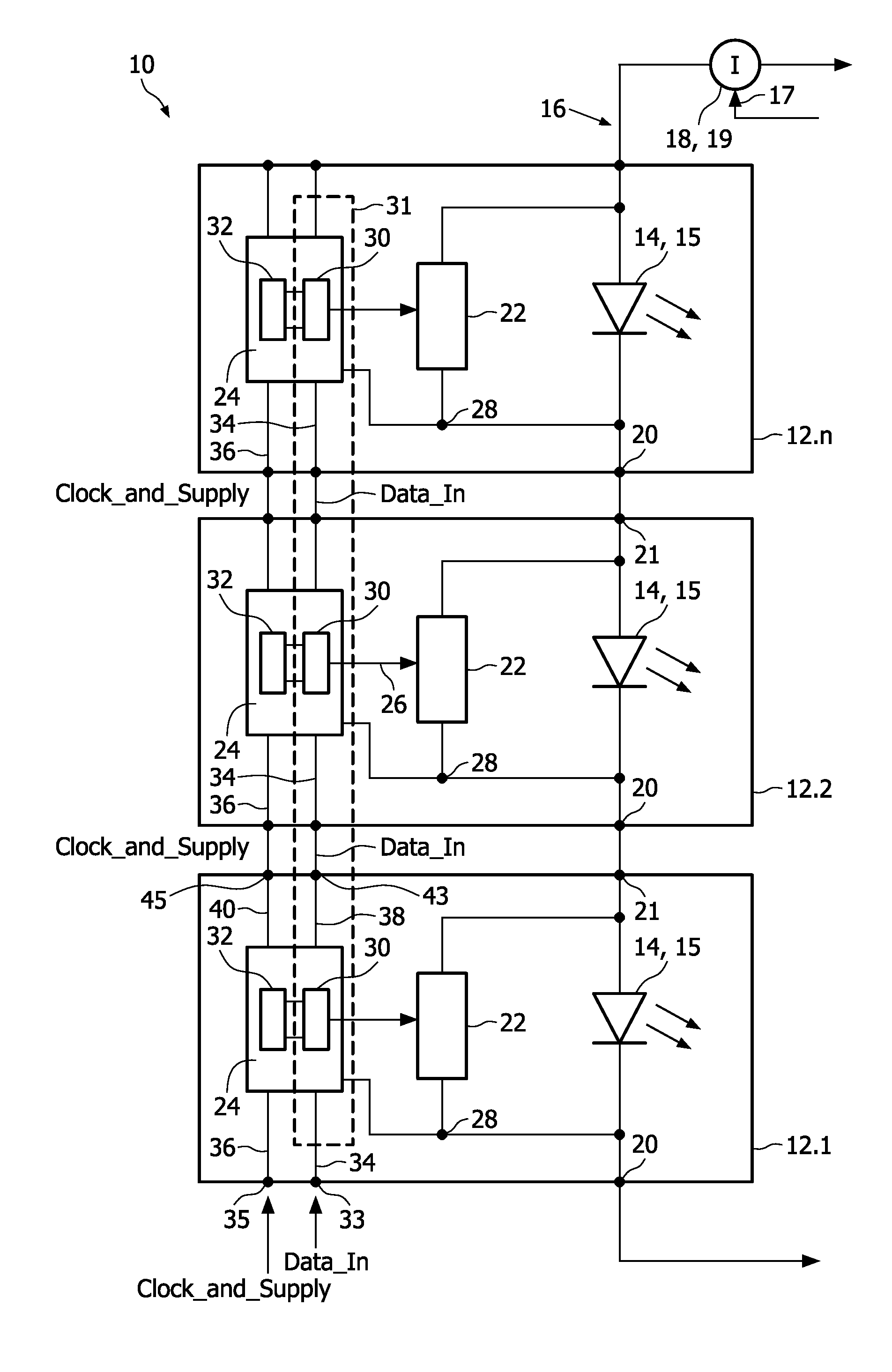
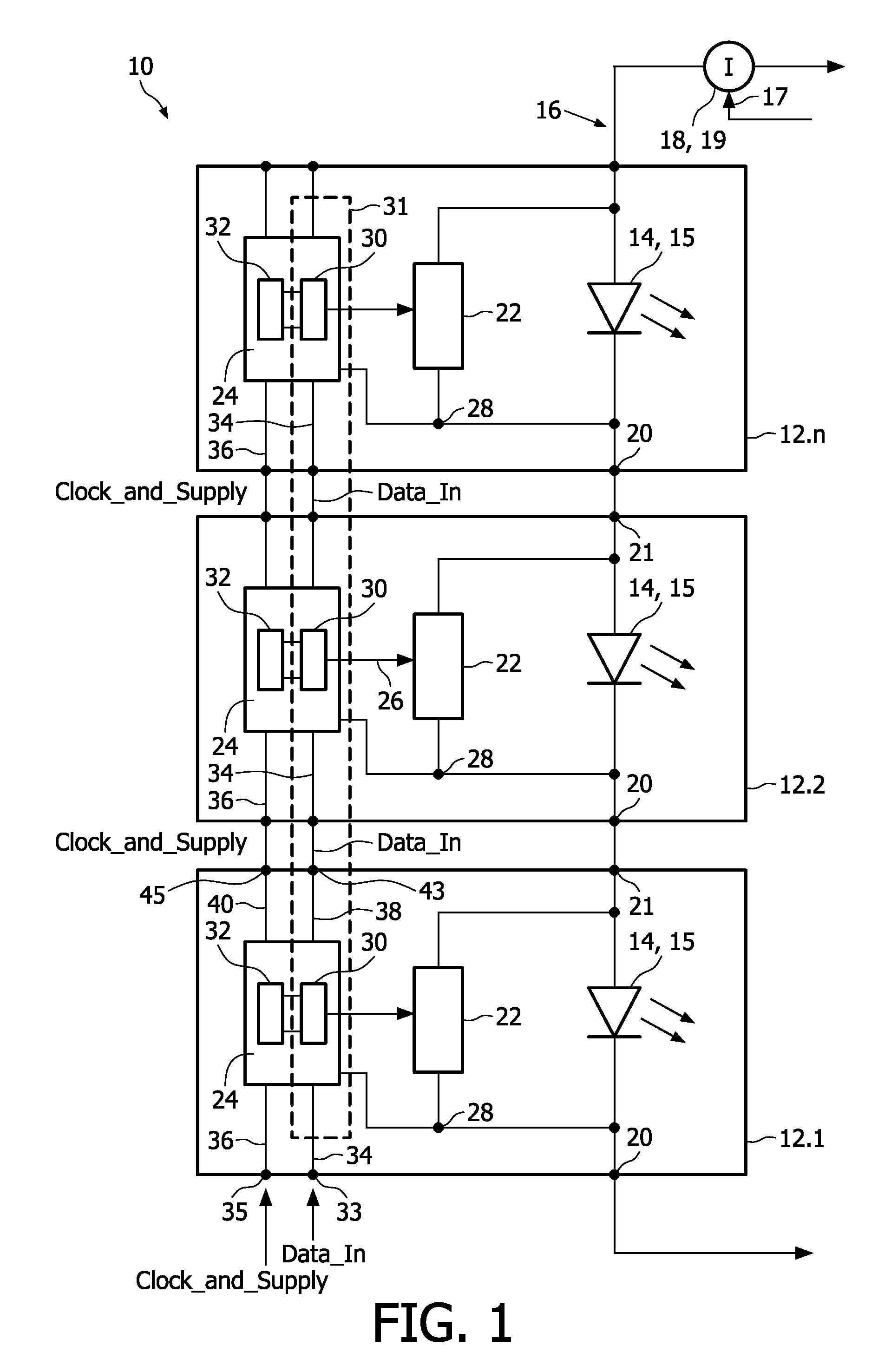
[0035]In FIG. 1, a driver device is schematically shown and indicated by means of reference numeral 10. The driver device 10 may be used for general illumination lamps with an enhanced control possibility or for pixelated lamps or to support spatial dimming or local highlighting in backlight and signage applications.

[0036]In particular, the driver device 10 is used in the shown embodiment to control light elements 14 which are coupled in series to form a string 16. The light elements 14 are provided as light emitting diodes 15 or organic light emitting diodes (OLED). Further, it is to be noted that each light element 14 may comprise one or more LEDs or OLEDs arranged in series, in parallel or a combination thereof. In the context of the following description, the expression LED 15 means generally a light element 14 of the afore-mentioned kind.

[0037]The LEDs 15 of the string 16 are powered by a power supply 18, which is for example a current source 19. The current source may be contr...


PUM


Abstract

The present invention relates to a device for individually driving OLED / LED elements of an OLED / LED string, comprising for each OLED / LED element of the string: a controllable shunting switch (22, 42) coupled with the respective OLED / LED element (14, 15), switch controller means (30, 44) for controlling said shunting switch (22, 42) and having a control output port coupled to said switch (22, 42), a data input port and a clock input port, level shifting means (32) assigned to said switch controller means (30, 44) and adapted to bring the control input data to a level sufficient to be accepted by the switch controller means (30, 44) during a programming mode and to allow the control of said shunting switch (22, 42). Said switch controller means (30, 44) of said OLED / LED elements (14, 15) are provided to form a serial-to-parallel converter means (31).

Description

FIELD OF THE INVENTION[0001]The present invention relates to a device for individually driving OLED / LED elements of an OLED / LED string. The invention also relates to a method of driving OLED / LED elements of an OLED / LED string individually.BACKGROUND OF THE INVENTION[0002]Lighting devices using LEDs or OLEDs (Organic Light Emitting Diode) gain more and more interest for general lighting applications. LEDs and OLEDs can be used to produce large amounts of light and have the benefit that they allow fast switching. On the one hand they can be used as general light sources, on the other hand they can be used as displays or design elements. In order to control the LEDs / OLEDs in a lighting device, so-called driver devices are used. In the art, there are a couple of solutions with respect to how to design such driver devices. For example, US 2006 / 0038803 A1 or WO 2006 / 107199 A2 disclose approaches regarding how to control LEDs coupled in series to form an LED string.[0003]Generally, using a...

Claims


Application Information

Patent Timeline
Patent Type & Authority Patents(United States)
IPC IPC(8): G09G3/36H05B41/16H05B44/00
CPCH05B33/083H05B37/0254H05B33/0896H05B45/48H05B45/60H05B47/18Y02B20/30
Inventor RADERMACHER, HARALD JOSEF GUENTHERWENDT, MATTHIAS
Owner SIGNIFY HLDG BV
Why Eureka
Try Eureka