Gas bearing spindle

a technology of gas bearings and spindles, which is applied in the direction of bearings, bearings, shafts, etc., can solve the problems of difficult support of rotation shafts, and achieve the effect of preventing deviation of retaining rings

Active Publication Date: 2012-04-24
NTN CORP
View PDF8 Cites 6 Cited by
  • Summary
  • Abstract
  • Description
  • Claims
  • Application Information

AI Technical Summary

Benefits of technology

[0019]The present invention is made to solve the above-described problems of the above-described conventional gas bearing spindle, and its object is to provide a gas bearing spindle capable of preventing deviation of a retaining ring when a compressed gas is supplied thereto.

Problems solved by technology

However, the above-described conventional gas bearing spindle has a problem as described hereinafter. FIGS. 6 and 7 are schematic cross sectional views showing one exemplary supporting structure of the sleeve in the conventional gas bearing spindle.
When each of sleeve gas supply paths 152 is thus blocked, the compressed gas cannot be supplied to bearing clearance 113, which disadvantageously makes it difficult to support rotation shaft 110 in a non-contact manner.

Method used


Image

  • Gas bearing spindle
  • Gas bearing spindle
  • Gas bearing spindle

Examples


first embodiment

[0049

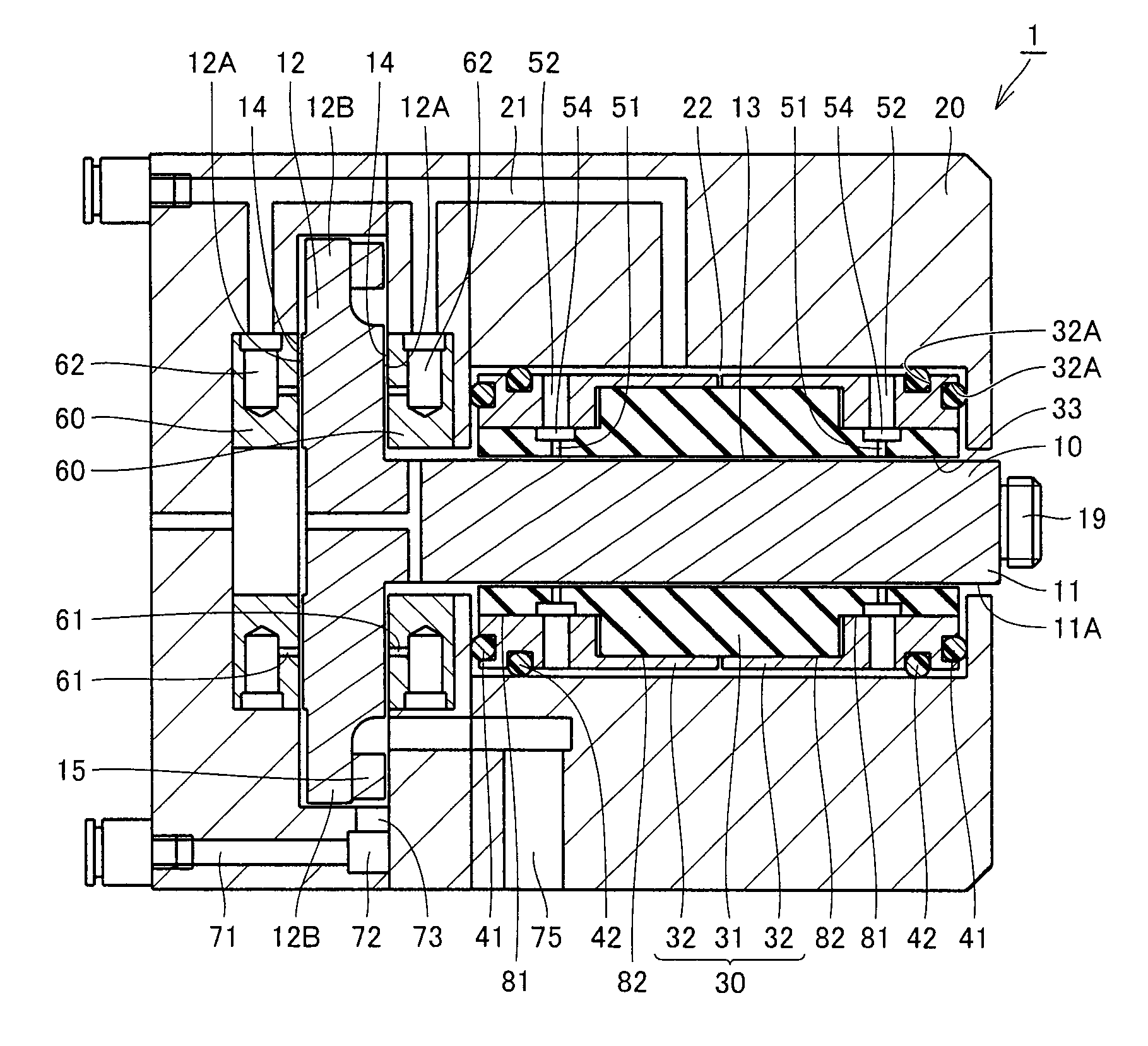
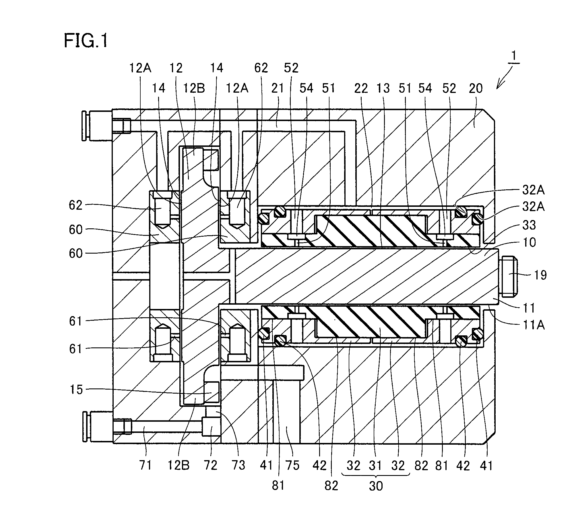
[0050]First, one embodiment of the present invention, a first embodiment, will be described. Referring to FIG. 1, a gas bearing spindle 1 in the first embodiment includes a rotation shaft 10; a sleeve 30 having a sleeve through hole 33, which is a cylindrical through hole that surrounds a portion of an outer circumferential surface 11A of rotation shaft 10; and a housing 20 surrounding sleeve 30 to retain sleeve 30 by means of O rings 41, 42 each serving as an elastic member and formed of a rubber. Rotation shaft 10 and sleeve 30 are disposed with a journal bearing clearance 13 of approximately 10 μm or greater but approximately 40 μm or smaller therebetween.

[0051]Rotation shaft 10 has a shaft portion 11 cylindrical in shape; and a flange portion 12 formed in one end of shaft portion 11 and having a large disk-like shape with a diameter larger than that of shaft portion 11. In the other end of shaft portion 11, a retaining unit 19 is formed to retain a tool or the like. Sleeve ...

second embodiment

[0069

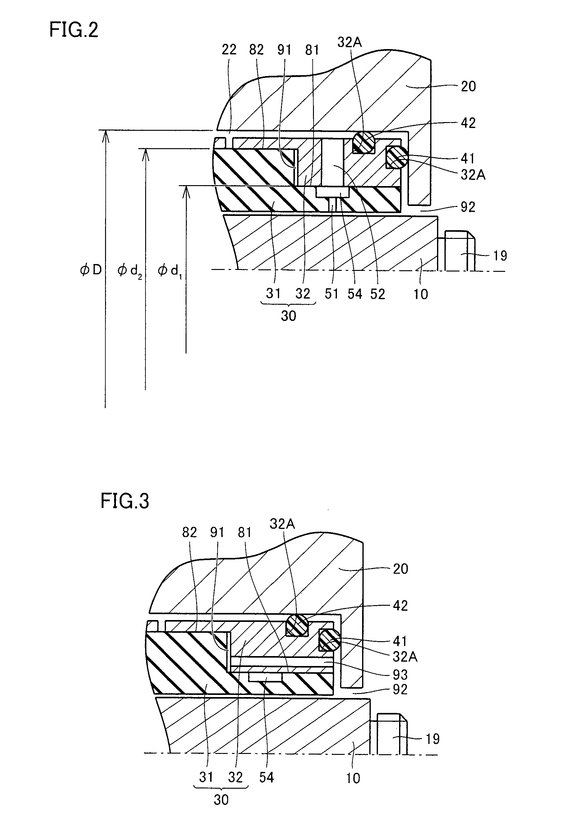
[0070]The following describes another embodiment of the present invention, a second embodiment. A gas bearing spindle 1 of the second embodiment has a configuration basically the same as that of gas bearing spindle 1 of the first embodiment, operates in a similar manner, and provides a similar effect. However, referring to FIG. 3, gas bearing spindle 1 of the second embodiment is different from gas bearing spindle 1 of the first embodiment in that a gas discharge path 93 is formed therein.

[0071]Specifically, in gas bearing spindle 1 of the second embodiment, a sleeve 30 is provided with gas discharge path 93 for connecting a boundary portion between each retaining ring 32 and a bearing portion 31 to a region located in gas bearing spindle 1 and open to external atmosphere. Via the boundary portion, a first fit surface 81 and second fit surfaces 82 are connected to one another. As described above, bearing portion 31 and retaining rings 32 are engaged with first fit surface 81 an...

third embodiment

[0073

[0074]The following describes still another embodiment of the present invention, a third embodiment. A gas bearing spindle 1 of the third embodiment has a configuration basically the same as that of gas bearing spindle 1 of the first embodiment, operates in a similar manner, and provides a similar effect. However, referring to FIG. 4, gas bearing spindle 1 of the third embodiment is different from gas bearing spindle 1 of the first embodiment in that a fit portion clearance 91 existing to connect first fit surface 81 and second fit surfaces 82 in sleeve 30 to one another is filled with a molding material 96 such as an adhesive agent.

[0075]Namely, in gas bearing spindle 1 of the third embodiment, the boundary portion between each retaining ring 32 and bearing portion 31, i.e., portion via which first fit surface 81 and each second fit surface 82 are connected to each other is filled with molding material 96.

[0076]Since the small fit portion clearance 91 exists in the boundary po...


PUM


Abstract

A gas bearing spindle includes a rotation shaft, a sleeve, and a housing. The sleeve includes a bearing portion formed of a nonmetallic sintered body; and a retaining ring formed of a metal. Further, the retaining ring and the bearing portion are in contact with each other at a first fit surface that is a boundary surface between the outer circumferential surface of the bearing portion and the inner circumferential surface of the retaining ring, as well as at a second fit surface that is a boundary surface between the outer circumferential surface of the bearing portion and the inner circumferential surface of the retaining ring, is distant further away from the sleeve through hole relative to the first fit surface, and is formed adjacent to a center of the sleeve through hole in a direction in which the sleeve through hole extends, when viewed from the first fit surface.

Description

BACKGROUND OF THE INVENTION[0001]1. Field of the Invention[0002]The present invention relates to a gas bearing spindle, more particularly, a gas bearing spindle used in precision machining equipment, a hole drilling machine, an electrostatic coating machine, or the like.[0003]2. Description of the Background Art[0004]In a gas bearing spindle including a gas bearing for supporting a rotation shaft relative to a housing by supplying a compressed gas such as compressed air to a small clearance between the rotation shaft and a member opposite to the rotation shaft within the housing, the rotation shaft is supported relative to the housing in a non-contact manner. Hence, not only friction loss is small in the bearing but also the member is not fatigued or worn out in a normal operation state because the rotation shaft and the member opposite to the rotation shaft are not in direct contact with each other. Taking advantage of such a feature, the gas bearing spindle is widely used as a hig...

Claims


Application Information

Patent Timeline
Patent Type & Authority Patents(United States)
IPC IPC(8): F16C32/06
CPCF16C32/067F16C32/0685F16C32/0614F16C2360/42
Inventor HIRATA, JUNICHI
Owner NTN CORP
Why Eureka
Try Eureka