Floating wind turbine with turbine anchor

a floating wind turbine and anchoring technology, which is applied in the direction of machine/engine, electric generator control, vessel construction, etc., can solve the problems of increasing the cost of the turbine, the more expensive the turbine becomes, and the more rigid the wind turbine is, and the blade length and width of the blade is practicable limi

Active Publication Date: 2012-04-24
BARBER GERALD L
View PDF31 Cites 13 Cited by
  • Summary
  • Abstract
  • Description
  • Claims
  • Application Information

AI Technical Summary

Benefits of technology

[0017]One of the wind turbine assemblies disclosed herein may include a floatable support, a pair of wind turbines mounted side-by-side on the floatable support and sail wings of one wind turbine each having a pitch opposite to the pitch of the sail wings of the other wind turbine to balance the gyroscopic effects of the wind turbines.
[0019]Another feature of a wind turbine assembly may include one or more wind turbines mounted on a floatable support with an anchor tied directly to the wind turbines to deter tilting of the wind turbines in response to strong wind directed into the wind turbines.

Problems solved by technology

The blades of the conventional wind turbines are very large and made of expensive rigid material and are constructed to have the blades extend radially from a central hub, with no extra support at the outer tips of the blades.
Since the outer portions of the blades move at a very high velocity and are engaged by strong winds, the larger the blades the stronger they must be and the more expensive they become.
Thus, there is a practical limit as to the length and width of the blades.
While wind turbines have found use in open land areas where steady winds are prevalent, the land areas most suitable for catching the wind on wind turbine propeller blades usually are remote from the areas of great need of electrical power.

Method used


Image

  • Floating wind turbine with turbine anchor
  • Floating wind turbine with turbine anchor
  • Floating wind turbine with turbine anchor

Examples


Embodiment Construction

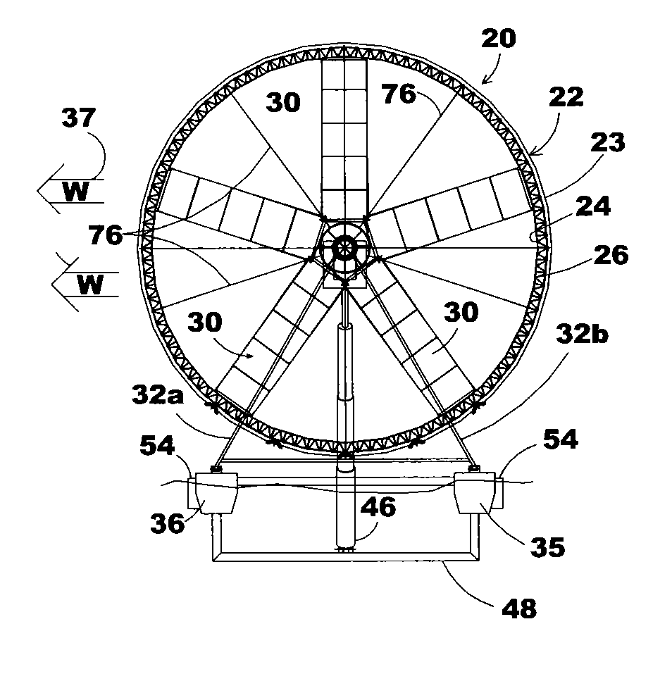
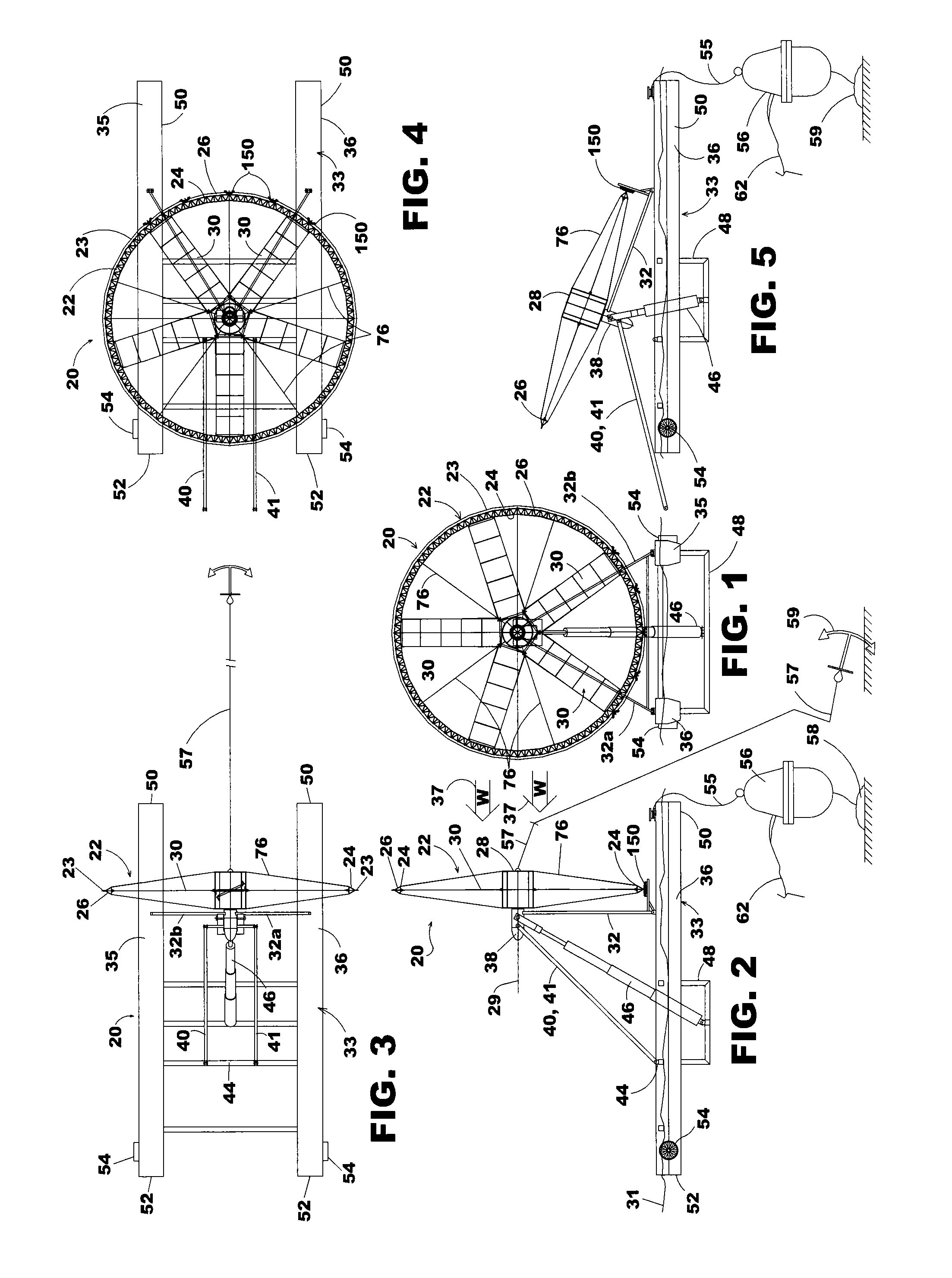
[0044]Referring now in more detail to the drawings in which like numerals indicate like parts throughout the several views, FIG. 1 shows a wind turbine 20 that is designed for catching the wind and rotating for the purpose of generating electricity. The wind turbine includes a turbine wheel 22 having an outer perimeter 23 formed by a series of angle braces 24 and an outer perimeter circular rim 26 that extends continuously about the turbine wheel. The outer perimeter circular rim may be formed of arcuate segments, and as explained in more detail hereinafter, the perimeter rim may function as the rotor of an electrical generator, or may function to drive a rotor of an electrical generator.

[0045]An axle structure 28 is at the center of the turbine wheel 22 and a plurality of sail wing assemblies 30 are mounted to the axle structure 28 and extend radially toward the angle braces 24 that form the perimeter of the turbine wheel. The turbine wheel rotates about the central axis 29.

[0046]T...


PUM


Abstract

The wind turbine 20 includes a wind driven turbine wheel 22 rotatable about a central axis 29 that has sail wings 30 that catch the wind and rotate the turbine wheel 22. An anchor 58 has its anchor line 56 attached to the turbine wheel at its axis of rotation 29 to prevent tilting the wind turbine in response to high wind conditions.

Description

CROSS REFERENCE TO RELATED APPLICATION[0001]This is a continuation-in-part of U.S. patent applications Ser. No. 12 / 426,494, filed on Apr. 20, 2009, and of Ser. No. 12 / 432,837, filed Apr. 30, 2009, and of Ser. No. 12 / 481,817, filed on Jun. 10, 2009.FIELD OF THE INVENTION[0002]This invention concerns a wind turbine assembly for generating electricity in response to the movement of atmospheric wind.BACKGROUND OF THE INVENTION[0003]Windmills have been used for many generations for the purpose of pumping water from the ground and for generating electricity. A basic advantage of the windmill is that it uses the power of atmospheric wind to rotate a wheel having radially extending blades. This rotary movement may be converted into various useful purposes. For example, wind turbines in the form of propellers mounted on towers have been placed in areas where steady winds are prevalent and the wind turbines are used to generate electricity.[0004]The blades of the conventional wind turbines ar...

Claims


Application Information

Patent Timeline
Patent Type & Authority Patents(United States)
IPC IPC(8): F03D9/00
CPCF03D9/002B63B21/48F03D13/25F03D9/25F05B2240/932F05B2240/95Y02E10/725Y02E10/727Y02B10/70Y02E10/721Y02B10/30F03D80/70Y02E10/72Y02P80/10F03D1/02
Inventor BARBER, GERALD L.
Owner BARBER GERALD L
Why Eureka
Try Eureka