Wind turbine system for buildings

a technology for wind turbines and buildings, applied in the direction of electric generator control, renewable energy generation, greenhouse gas reduction, etc., can solve the problems of increasing bearing wear, turbine turning relatively slowly, and never progressing beyond the research stag

Inactive Publication Date: 2008-01-01
GRAHAM SR JOHN F
View PDF14 Cites 55 Cited by
  • Summary
  • Abstract
  • Description
  • Claims
  • Application Information

AI Technical Summary

Benefits of technology

[0013]In one embodiment, a power-generating wind turbine structure is placed at (on or near) the edge of a building's rooftop. The device may employ a variety of different turbine styles, including straight-wing or cylindrical types (as will be described in more detail below,) propeller-style, or any other type. The axis of rotation is parallel to the ground and parallel to the edge of the building. The placement of the turbine structure near the edge of the building allows it to use the building wall as a passive concentrator to funnel wind up the face of the building and into the turbine structure. A concentrator may be used to help catch and direct rising winds into the turbine. Turbines can be installed on multiple sides of the building to optimize the system for variations in wind direction with changes in seasons or weather conditions.
[0014]In one embodiment, the wind turbine has a cylindrical turbine structure, and the turbine is oriented with its axis parallel to the edge of the roof. The wind turbine may be positioned adjacent to a parapet wall, so that the parapet wall screens at least a portion of the negative wind flow from the turbine as the blades rotate. A deflector may be attached to the parapet wall or the turbine itself to redirect the concentrated wind flow toward a desired portion of the wind turbine to increase efficiency. In one embodiment, the wind turbine is coupled to a generator which generates electricity when driven by the wind turbine. The system may include a concentrator to redirect wind flow over the edge of the roof to a desired portion of the wind turbine. The concentrator may be adjustably positioned to enhance or spoil wind flow to the wind turbine. The system may also include solar cells mounted on the concentrator and configured to generate electricity from sun light contacting them. The system may further include a deflector positioned on the side of the wind turbine opposite the edge of the roof to redirect wind flow originating opposite the edge of the roof to a desired portion of the wind turbine enabling the turbine to utilize the wind from multiple directions.

Problems solved by technology

In addition to keeping the turbine erect, the cables impose a large thrust loading on the main turbine bearings, causing increased wear on the bearings.
The cylcoturbine was marketed commercially for several years, but never progressed beyond the research stage.
The turbine turns relatively slowly, but yields high torque.
It has been proven useful for pumping water and other tasks, but its slow rotational speeds have not been proven to generate electricity cost effectively from wind power.
Augmentors or concentrators have also been developed to try to concentrate wind onto the turbines, but they have not been proven to be economically successful in commercial use.

Method used


Image

  • Wind turbine system for buildings
  • Wind turbine system for buildings
  • Wind turbine system for buildings

Examples


Embodiment Construction

[0023]One or more embodiments of the invention are described below. It should be noted that these and any other embodiments described below are exemplary and are intended to be illustrative of the invention rather than limiting.

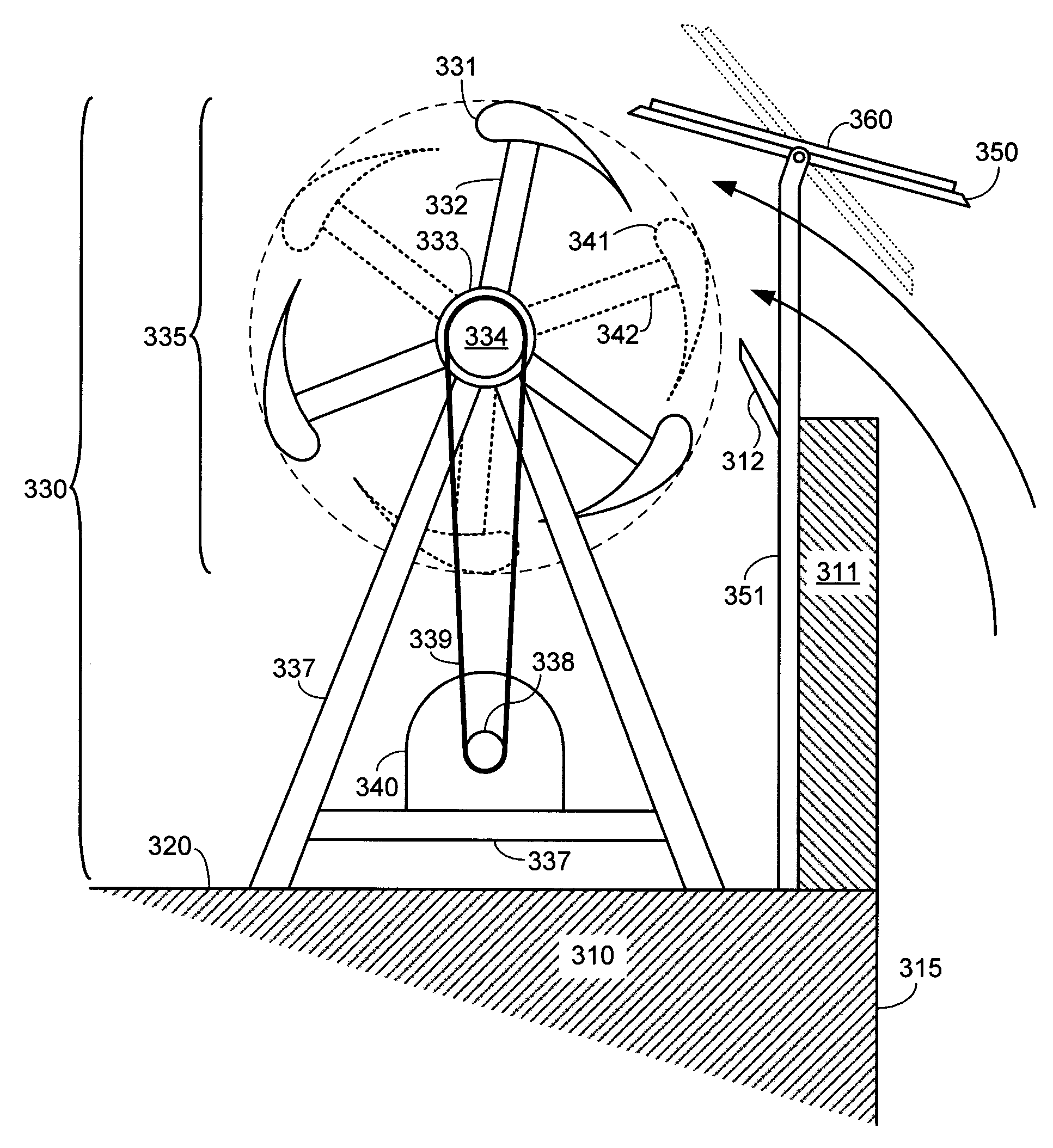
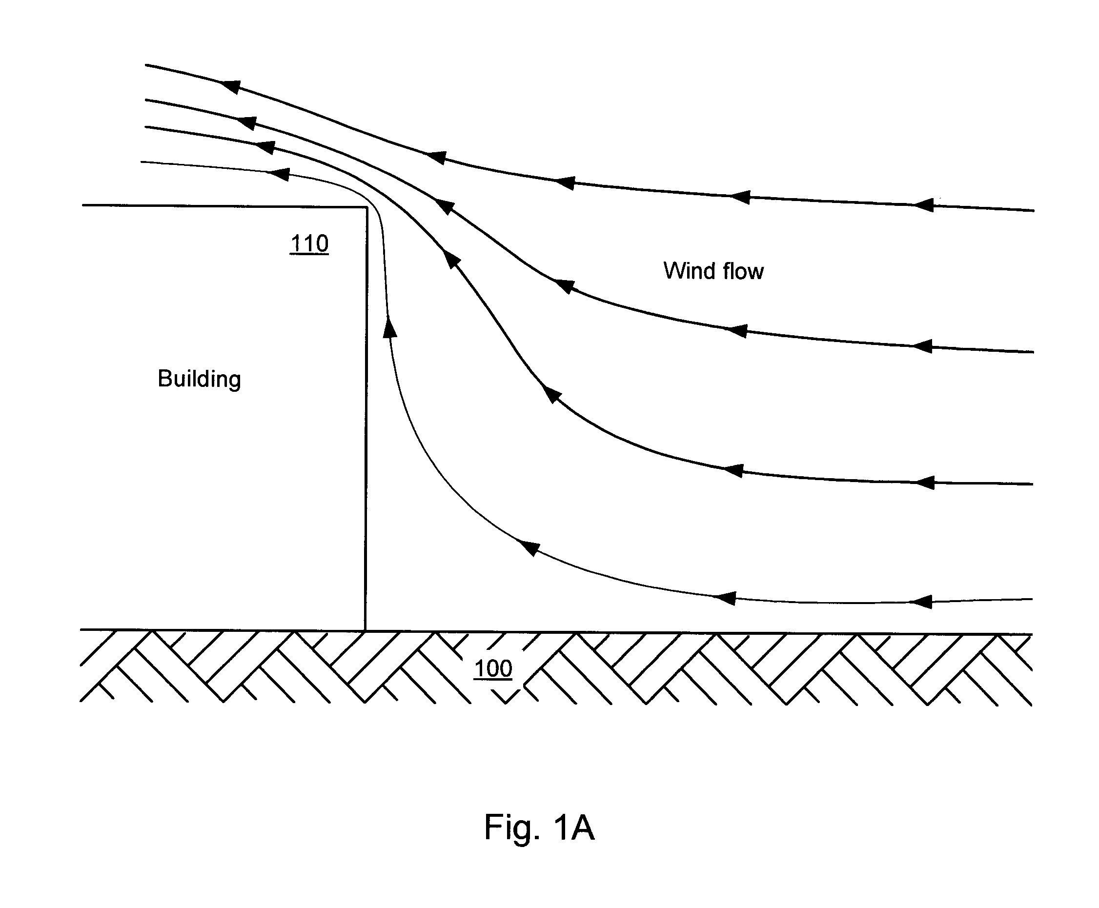
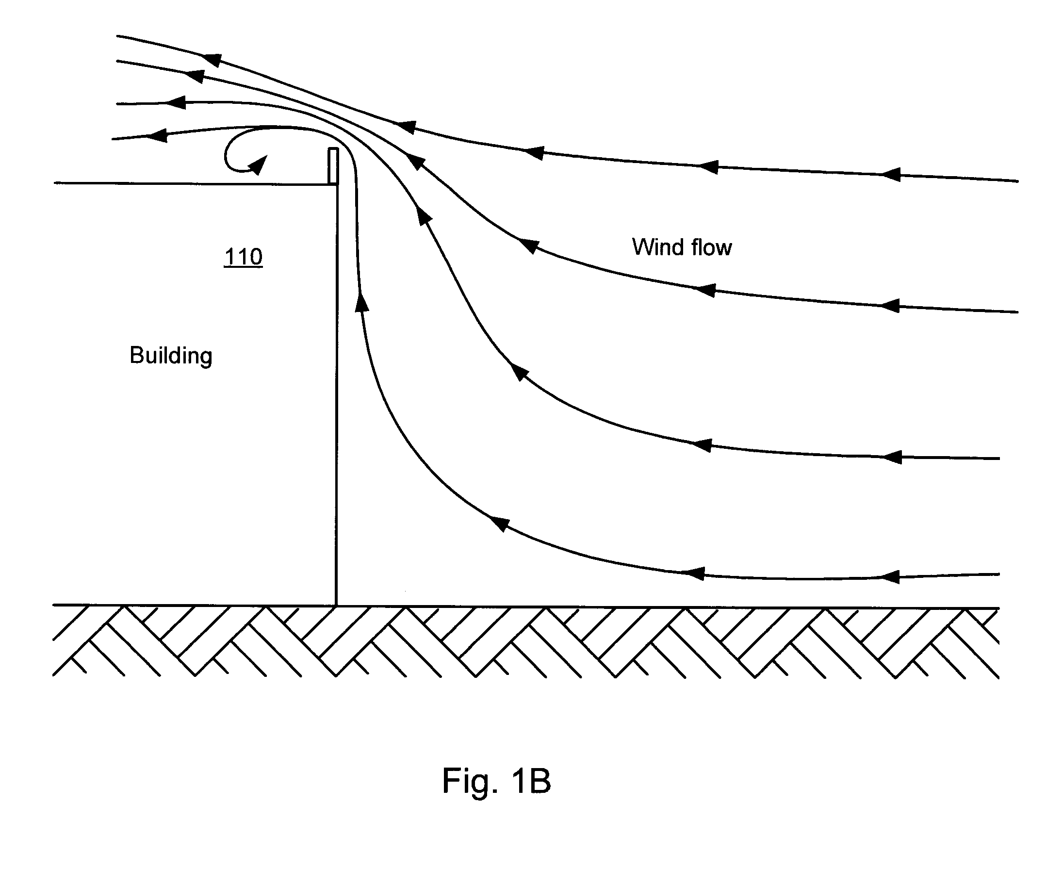
[0024]As described herein, various embodiments of the invention comprise systems and methods for capturing the energy of wind currents by placing wind-driven turbines at one or more edges or the perimeter of a building's roof, where the wind currents are concentrated by deflection of the wind off the vertical faces of the building.

[0025]In one embodiment, an energy generation system makes use of a cylindrical turbine having multiple blades that are parallel to the axis (axis of rotation) of the turbine. The turbine is positioned on the roof of a building, near the edge of the roof on its perimeter. The turbine is oriented horizontally, with its axis parallel to the edge of the roof. In this embodiment, a parapet wall extends upward from the edge of the roof. ...


PUM


Abstract

Systems and methods for capturing the energy of wind currents by placing wind-driven turbines at one or more edges of a building's roof, where the wind currents are concentrated by deflection of the wind off the horizontal faces of the building. In one embodiment, a cylindrical wind turbine is placed at the edge of a building's rooftop. The turbine structure drives an electrical generator. The axis of rotation of the turbine is parallel to the ground and to the edge of the building. A concentrator may be used to direct rising winds into the turbine. Turbines can be installed on multiple sides of the building to optimize the system for variations in wind direction with changes in seasons or weather conditions.

Description

RELATED APPLICATIONS[0001]This application claims the benefit of U.S. Provisional Patent Application Ser. No. 60 / 763,615 by John F. Graham, filed Jan. 31, 2006, which is hereby incorporated by reference as if set forth herein in its entirety.BACKGROUND[0002]1. Field of the Invention[0003]The invention relates generally to wind turbines, and more particularly to systems and methods for positioning wind turbines at the edges of building roofs in order to utilize concentrated wind flow at the edge of the roof for purposes such as electricity generation.[0004]2. Related Art[0005]Wind turbines of many types have been used to generate electricity in a variety of ways. The prior art describes turbines in a variety of locations including natural ridgelines, open fields, mesas and on ships. Recent design concepts for rebuilding the World Trade Center showed plans to incorporate wind turbines in that structure to harness the electrical generating power of passing winds. These turbines for gen...

Claims


Application Information

Patent Timeline
Patent Type & Authority Patents(United States)
IPC IPC(8): F03D9/00
CPCF03D3/002F03D3/0436F05B2240/2212F05B2240/911F05B2240/9112Y02B10/30Y02E10/728Y02E10/74F03D3/02F03D3/0454F03D9/007F03D9/25F03D9/34F03D15/10H02S10/12Y02B10/10Y02E10/50
Inventor GRAHAM, SR., JOHN F.
Owner GRAHAM SR JOHN F
Why Eureka
Try Eureka