Laminar air turbine

a technology of laminar air turbines and wind turbines, which is applied in the direction of machines/engines, stators, liquid fuel engines, etc., can solve the problems of ineffective utilization of wind energy, inability to achieve optimal output for the full dynamic range of fluctuating winds, and limitations of conventional design approaches, etc., to achieve the effect of maximizing the rotational force, generating power, and low cos

Inactive Publication Date: 2007-05-08
RICHTER DONALD L
View PDF37 Cites 55 Cited by
  • Summary
  • Abstract
  • Description
  • Claims
  • Application Information

AI Technical Summary

Benefits of technology

[0008]The present invention is directed to devices that accelerate the air stream before it is captured and directed toward the turbine blades to extract energy and generate power. Similarly, efficient water turbines do not “just take the fluid as it comes” out of the end of a hose to turn a turbine and generate electricity. They first accelerate the water stream through a nozzle before it blasts the turbine blades. The present invention does not just “take the wind as it comes.” The present invention provides a novel system to accelerate the wind before it blasts the turbine wheel blades to generated electricity. It is a novel wind power generator in the form of a relatively low cost turbine that includes a rotor and apparatus for directing the airflow to maximize the rotational force applied to the rotor blades. The wind driven turbine of the present invention further provides a modular construction that permits it to be assembled quickly by semiskilled workers without need for costly and sophisticated equipment, and provides a high power-to-weight ratio at relatively low cost and without sacrifice of structural integrity.
[0010]This invention relates to devices and methods for improving the efficiency of wind driven turbines to generate electric power, and, in particular, to a turbine design that augments the air stream directed towards the blades of the turbine. The present invention relates broadly to apparatus for increasing the flow speed of a medium such as air or water and for recovering its kinetic energy. The invention is described below with reference to wind as the medium, but it will be appreciated that the invention with modifications that are well known to those of ordinary skill in the art is applicable also to a medium such as water. The present power-generating wind-driven turbine offers the advantage that it is compact and lightweight and is capable of producing a substantially greater output than a conventional windmill with a comparable size rotor. The laminar air turbine is configured with an aerodynamic nose in front of a cowling and fixed vanes. The nose and cowling form a streamlined wind-collecting duct designed to turn and accelerate the air stream into the turbine blades. The turbine wheel duct is configured with an array of curved energy capturing blades and an exit section designed to exhaust the air stream into the tail section and beyond with a minimum of turbulence. The present tail assembly is configured to turn the exit air inward toward the tail. Unlike heretofore known windmills, the tail section of the windmill of the present invention includes a series of perimeter vanes inside a duct fixed to the stationary tail to turn the slower exit air parallel to the wind and inward along the tapered tail to follow the wind and eliminate energy stealing swirls.
[0013]Unlike the nosecones of typical propeller bladed windmills that are shaped to reduce the hub wind-drag and protect the generator, the nose of the present invention is specially shaped to accelerate the wind around the nose as a thin laminar layer of fast moving air into the perimeter turbine blades. Unlike typical windmills whose blades spin the supporting shaft to transfer power, the turbine wheel in this invention spins freely on a stationary backbone axle. Unlike typical propeller windmills, the blades and vanes of the present invention are enclosed in a duct to prevent energy losses due to vortex shedding and trailing swirls.
[0015]Unlike the Venturi based windmills, and all other known vertical or horizontal axis windmills that use blades that deflect the wind significantly less than ninety degrees; the present invention turbine blades turn the wind significantly more than ninety degrees for optimum power output. Unlike propeller bladed windmills, Venturi based windmills, and all other known windmills, the present invention provides for the use of several perimeter mounted electric generators that can be sequentially turned on or off in response to varied winds to safely hold the turbines and generators speed at their highest levels of power production. Unlike any other known windmill, the present invention has counter-rotating belts of turbine wheels that are light and stable enough to be wrapped around large blimp like bodies and that use the laminar air principle to efficiently generate large quantities of electric power in the fast and stable winds at higher elevations.

Problems solved by technology

However, there are some limitations with that conventional design approach.
Using twisted (variable pitch) blades help accommodate the rotational speed difference between the hub and the blade tip, but it cannot perform with optimal output for the full dynamic range of the fluctuating winds.
In many areas of the world, the predominant wind speed is at or only slightly above the level required for economical energy recovery and, therefore, wind energy has not been harnessed effectively.
Further, increasing the diameter of the propeller decreases the rotational speed of the windmill.
The longer blades are more difficult and costly to make so they must be light in weight, properly shaped and capable of responding to the prevailing wind without undergoing excessive deflection, distortion or failure.
However, such known designs have the disadvantage that most of the oncoming air does not enter the funnel but would flow around the outside due to backpressure.
Further, the small amount of air that does pass through the funnel would be directed at the central area around the hub of the windmill where it would be least effective in generating power.
No prior known wind turbine systems have utilized the approach of first accelerating the wind in a laminar flow around a streamlined body before it captures the accelerated air and sends it through the circumferentially mounted turbine blades.

Method used


Image

  • Laminar air turbine
  • Laminar air turbine
  • Laminar air turbine

Examples


Embodiment Construction

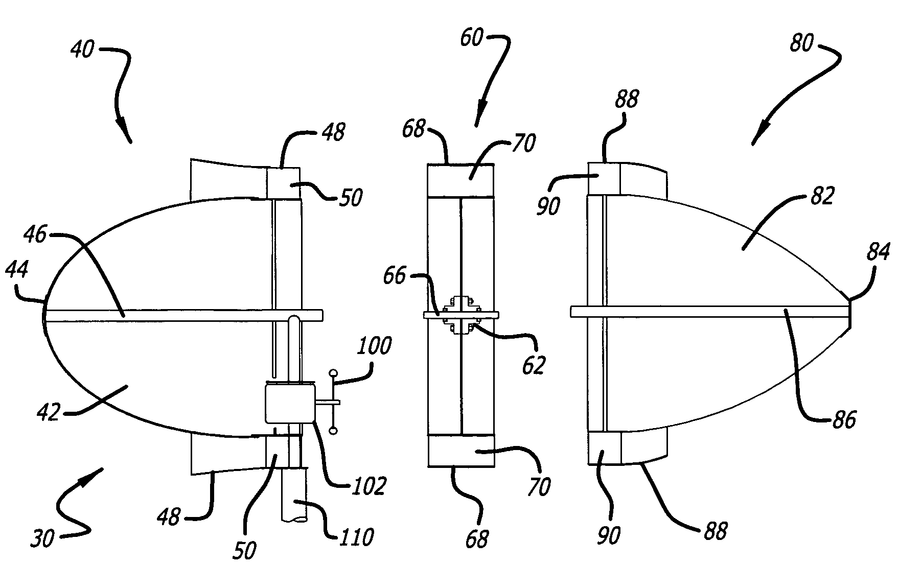
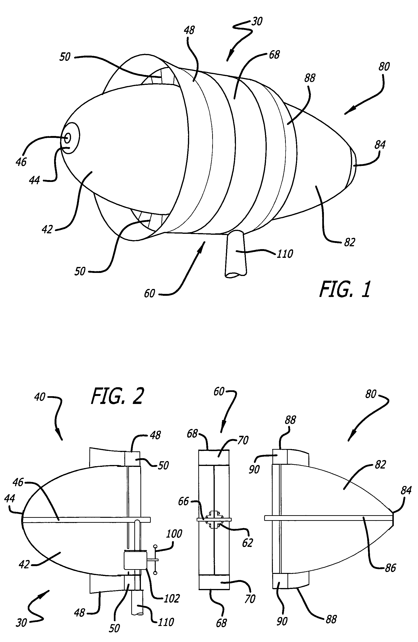
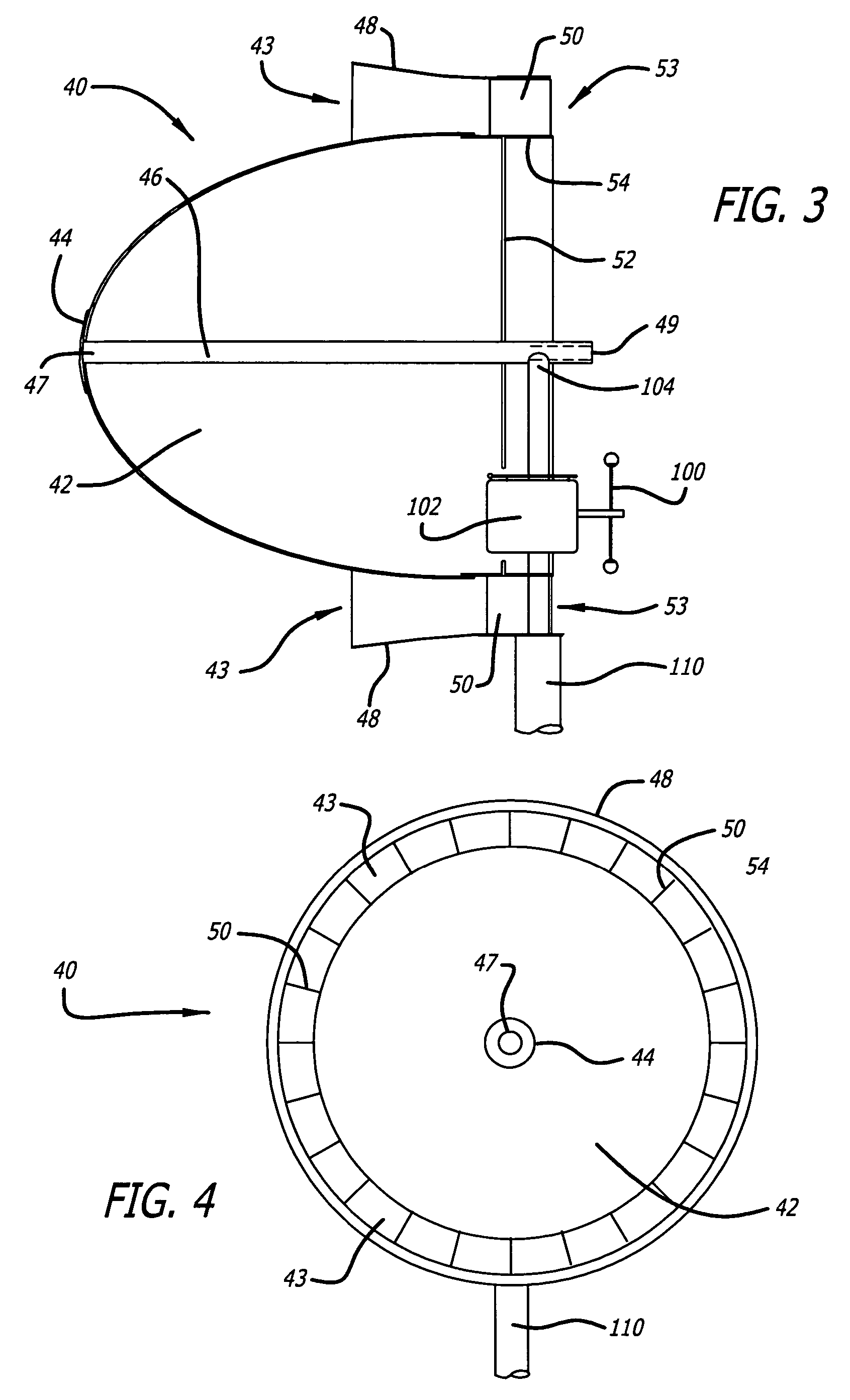
[0031]The present invention is directed to a minimum drag, streamlined body-of-revolution having a rounded nose and tapered tail halves that are separated for the insertion of one or more rows of turbine wheels. The present invention inserts one or more rows of ducted turbine wheels between the low-drag nose and tail halves to capture that accelerated laminar wind close to the body and to send that accelerated wind through the turbine blades to generate electricity. In principle, the less a wind stream is disturbed as it passes a stationary body the lower its wind drag force will be. A streamlined body-of-revolution achieves the lowest drag by separating the wind at the rounded nose, causing it to accelerate around the body in a smooth laminar fashion so as to merge at the tail with the surrounding wind, with minimum induced turbulence. The subject windmill can be described as a low drag, streamlined body in which the accelerated laminar air surrounding the body is captured for its ...


PUM


Abstract

The windmill assembly is a low drag, streamlined body of revolution that captures the kinetic energy content of the accelerated laminar air surrounding the body. The assembly includes a power-generating, wind-driven turbine that is compact, lightweight and capable of producing a substantially greater output than a conventional windmill with a comparable size rotor. The turbine includes a protruding aerodynamic nose and outer cowling that provide a streamlined, wind-collecting inlet section that constricts the incoming air stream and increases its velocity through the turbine blades. The turbine further includes an exit section designed to exhaust the air stream with a minimum of turbulence. One or more generators are coupled to a turbine wheel, and are electrically switched on and off to maximize the energy capture over the full range of ambient winds. The wind turbine assembly may be configured around a blimp-type body having counter-rotating turbine assemblies.

Description

BACKGROUND OF THE INVENTION[0001]This invention relates to a new wind driven turbine with improved efficiency to generate electric power, and in particular to a turbine design that augments the fluid stream towards the blades of the turbine. The present invention relates broadly to apparatus for increasing the flow speed of a fluid medium such as air or water and for recovering its kinetic energy. This invention further relates to the harnessing of wind power for converting kinetic wind energy to mechanical and / or electrical power. The present invention is described with reference to wind as the medium; however, those of ordinary skill in the art will appreciate that the invention is applicable to other fluid mediums (e.g., gases and liquids), such as steam and water.[0002]Because energy from the wind is free and non-polluting, much affention has been given to improving the efficiency and lowering the cost of windmill structures. Energy has been extracted from moving air for thousan...

Claims


Application Information

Patent Timeline
Patent Type & Authority Patents(United States)
IPC IPC(8): F03D1/04
CPCF03D1/025F03D1/04F03D7/0236F05B2240/124F05B2240/13F05B2240/133F05B2240/313F05B2240/914F05B2240/922F05B2240/98F05B2270/20Y02E10/721Y02E10/723Y02E10/728F03D13/10F03D9/25Y02E10/72
Inventor RICHTER, DONALD L.
Owner RICHTER DONALD L
Why Eureka
Try Eureka