Method for adapting a wind energy installation to given wind conditions

a technology of wind energy installation and wind energy, which is applied in the direction of material dimension control, non-positive displacement fluid engine, liquid fuel engine components, etc., can solve the problems of inert method, insufficient wind energy installation regulation, and severe influence of wind conditions, etc., and achieve the effect of short response tim

Inactive Publication Date: 2007-03-22
VOLKSWIND
View PDF13 Cites 54 Cited by
  • Summary
  • Abstract
  • Description
  • Claims
  • Application Information

AI Technical Summary

Benefits of technology

[0007] One object of the present invention is, in particular, to specify a method for adapting a wind energy installation to given wind conditions of the type mentioned initially, in which particularly short response times of t

Problems solved by technology

One disadvantage with the measurement of the wind using the rear end of the pod is in particular the fact that the wind conditions present there are severely influenced by the rotor, in particular the rotor blades, which is arranged upstream of the wind vane based on the wind flow.
The result of this is the fact that the regulation of the wind energy installations is often not optimal.
One disadvantage with this prior art is in particular the inertia of the method.
The wind energy installation only

Method used


Image

  • Method for adapting a wind energy installation to given wind conditions
  • Method for adapting a wind energy installation to given wind conditions
  • Method for adapting a wind energy installation to given wind conditions

Examples


Embodiment Construction

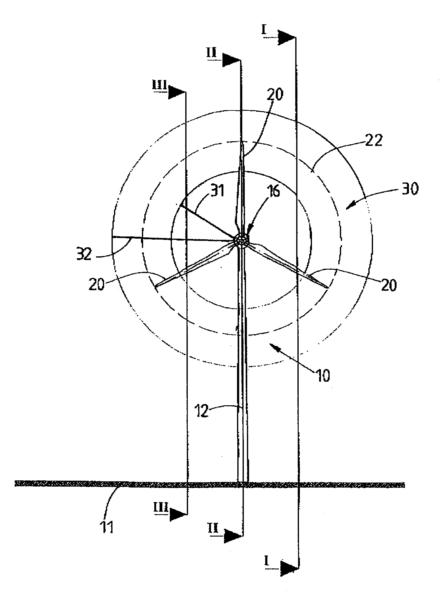
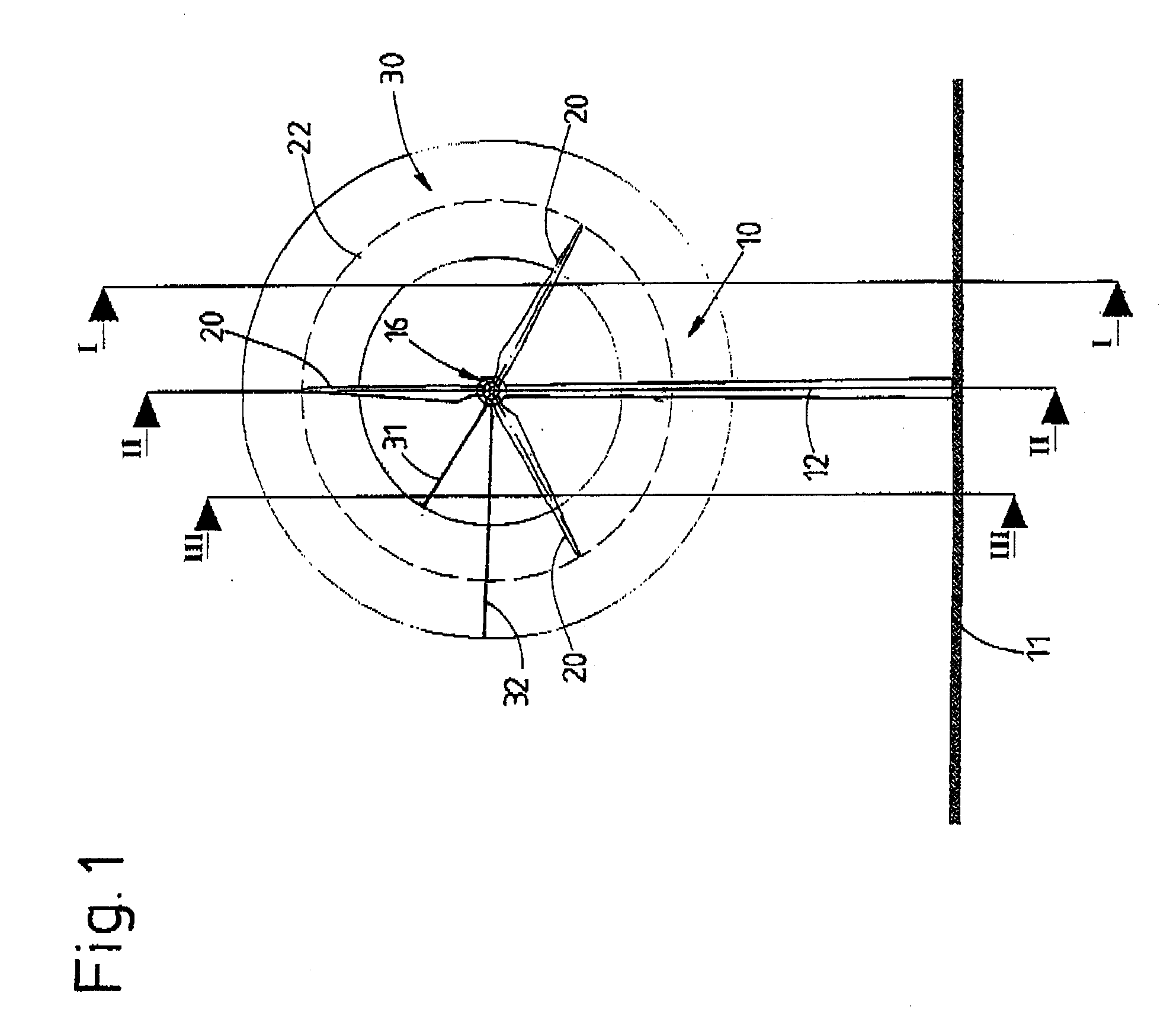
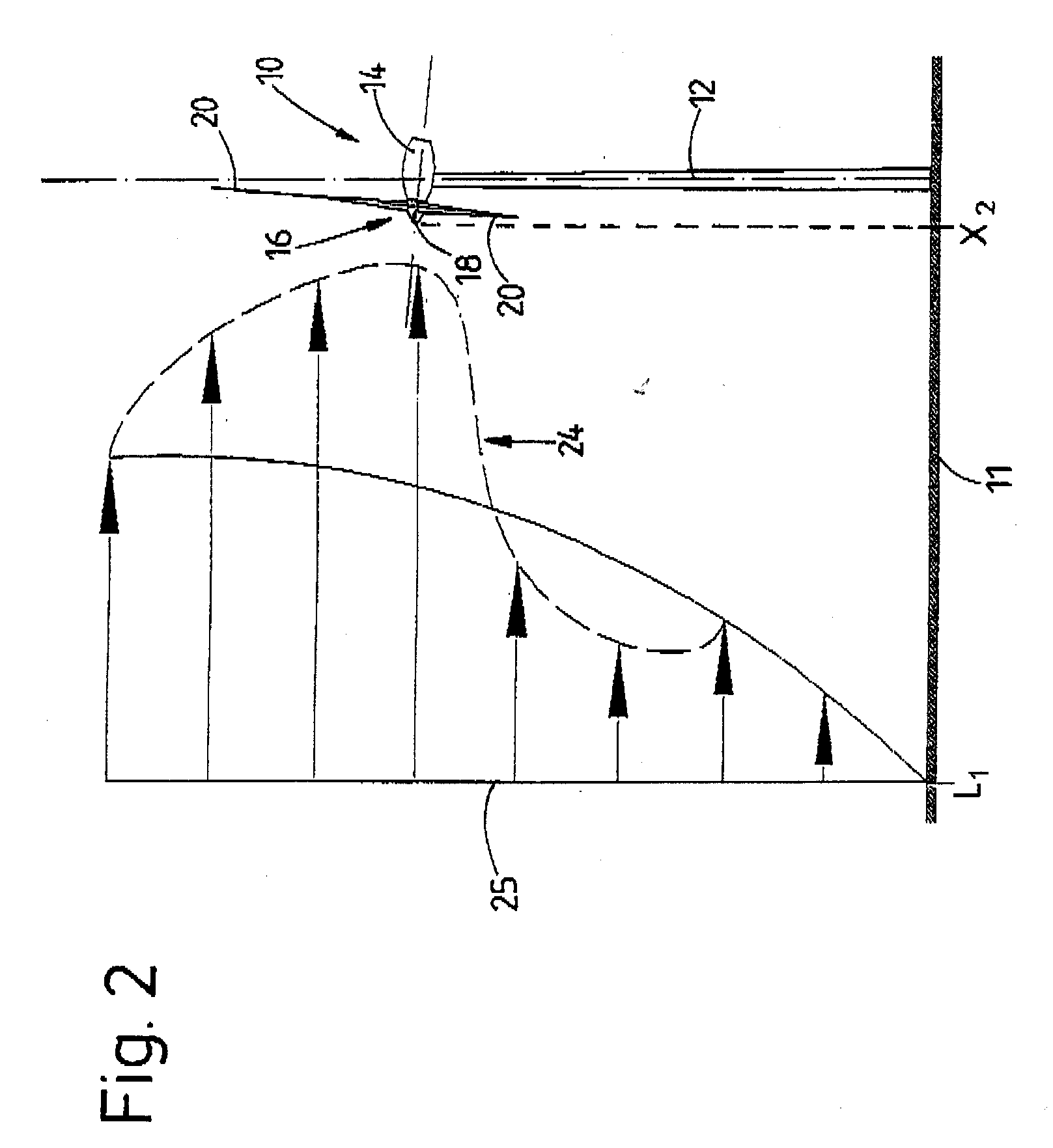
[0072]FIGS. 1-4 show a wind energy installation 10 which, at the end of a vertical tower 12 arranged on a horizontal base 11, has a pod 14 arranged on the upper side of the tower. A rotor 16, which has a hub 18, is arranged at an end facing the wind of the pod 14. Three rotor blades 20 of the rotor 16 are connected to the hub 18, the rotor blade bases of the rotor blades 20 being inserted into corresponding openings in the hub 18 and being connected to said hub in a known manner.

[0073] The rotor 16 rotates about an axis which is slightly upwardly inclined with respect to the horizontal. As soon as wind hits the rotor blades 20, the rotor 16 together with the rotor blades 20 is set in rotation about the rotor axis. The rotor blades 20 in the process cover an imaginary circular area 22, whose contours are illustrated by dashed lines. The rotor blades 20 can be altered individually in terms of their position in relation to the wind, i.e. the angle of incidence of the rotor blades 20 i...


PUM


Abstract

A method for operating a wind energy installation, in particular for adapting a wind energy installation (10) to given wind conditions, the wind energy installation (10) having a rotor (16), which can be driven by wind, with at least two rotor blades (20), whose respective angles of incidence of the wind can be adjusted by means of at least one adjustment device, and having a generator for converting the mechanical energy of the rotor (16) to electrical energy. During operation of the wind energy installation, parameters are measured with spatial and/or temporal resolution on the side of the wind energy installation (10) facing the wind, said parameters describing the wind conditions in the measurement region, preferably the wind speed and/or the wind direction. The wind parameters are measured at various vertical distances from the ground, namely various heights, and at horizontal distances from the rotor (16), which are selected such that the angles of incidence of the wind on the individual rotor blades (20) can be adapted in response to the measured wind parameters before the wind on which the wind parameters are based, in particular a wind front or a gust of wind, reaches the rotor (16). Values are predicted or calculated, in particular continuously or periodically, from the measured wind parameters—prognosis values—which describe wind conditions occurring in the future at the rotor blades for various heights. The angles of incidence of the wind on the individual rotor blades (20) are adjusted individually and independently of one another, preferably a plurality of times during a complete revolution of a rotor blade, depending on these predicted or calculated prognosis values at the various heights.

Description

STATEMENT OF RELATED APPLICATIONS [0001] This patent application claims convention priority on German Patent Application No. 10 2005 045 516.6 having a filing date of 22 Sep. 2005, which is incorporated herein by this reference. BACKGROUND OF THE INVENTION [0002] 1. Technical Field [0003] The present invention relates to a method for operating a wind energy installation, in particular for adapting a wind energy installation to given wind conditions, the wind energy installation having a rotor, which can be driven by wind, with at least one rotor blade, and having a generator for converting the mechanical energy of the rotor to electrical energy. Furthermore, the invention relates to a method for operating a windpark comprising such wind energy installations and to a wind energy installation having a control / regulation device for carrying out the abovementioned method. [0004] 2. Prior Art [0005] It is known to regulate wind energy installations depending on given wind conditions or t...

Claims


Application Information

Patent Timeline
IPC IPC(8): F03D9/00H02P9/04
CPCF03D7/0224Y02E10/723F03D7/028F03D7/042F03D7/048F05B2240/95F05B2260/821F05B2270/1033F05B2270/20F05B2270/32F05B2270/321F05B2270/322F05B2270/404F05B2270/806F03D7/024Y02E10/72Y02E10/727
Inventor STOMMEL, MATTHIAS
Owner VOLKSWIND
Why Eureka
Try Eureka