Fracture fixation system

a fracture fixation and system technology, applied in the field of medical devices, can solve problems such as inadequacies or impractical applications, and achieve the effect of rapid patient recovery and significant initial structural integrity

Active Publication Date: 2012-05-22
TOBY ORTHOPAEDICS
View PDF116 Cites 42 Cited by
  • Summary
  • Abstract
  • Description
  • Claims
  • Application Information

AI Technical Summary

Benefits of technology

[0008]The present invention is directed to a bone fixation system including a plate portion and a rod portion configured for significant initial structural integrity and rapid patient recovery.
[0010]A further object of the present invention is to provide a fracture fixation system incorporating a plurality of screws configured and placed so as to maximize imbedded screw depth into bone structure having the greatest density.
[0012]An additional object of the present invention is to provide a fracture fixation system utilizing fasteners configured for divergent angle placement in order to provide increased structural load resistance.

Problems solved by technology

Although a variety of different approaches have been attempted in the past, existing solutions have consisted basically of familiar, expected, and obvious structural configurations that have proven to be inadequate or impractical in application.

Method used


Image

  • Fracture fixation system
  • Fracture fixation system
  • Fracture fixation system

Examples


Embodiment Construction

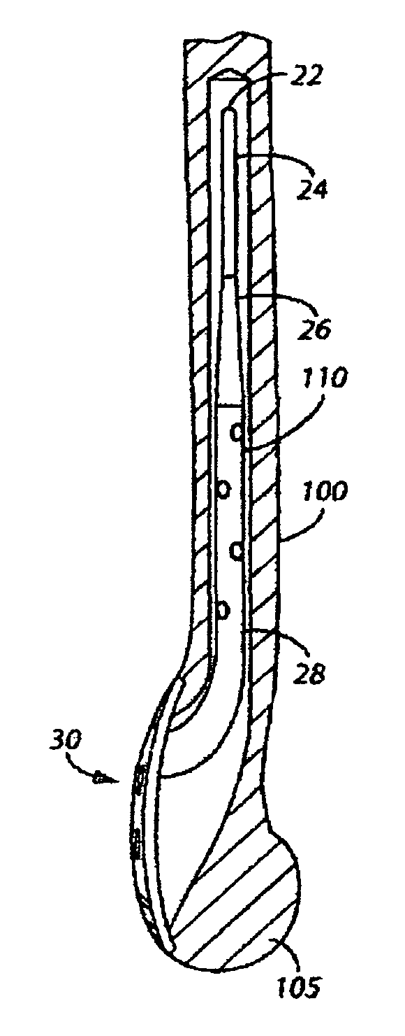
[0028]Shown throughout the figures, the present invention is generally directed to a fracture fixation system configured towards treating a variety of different human bone fractures.

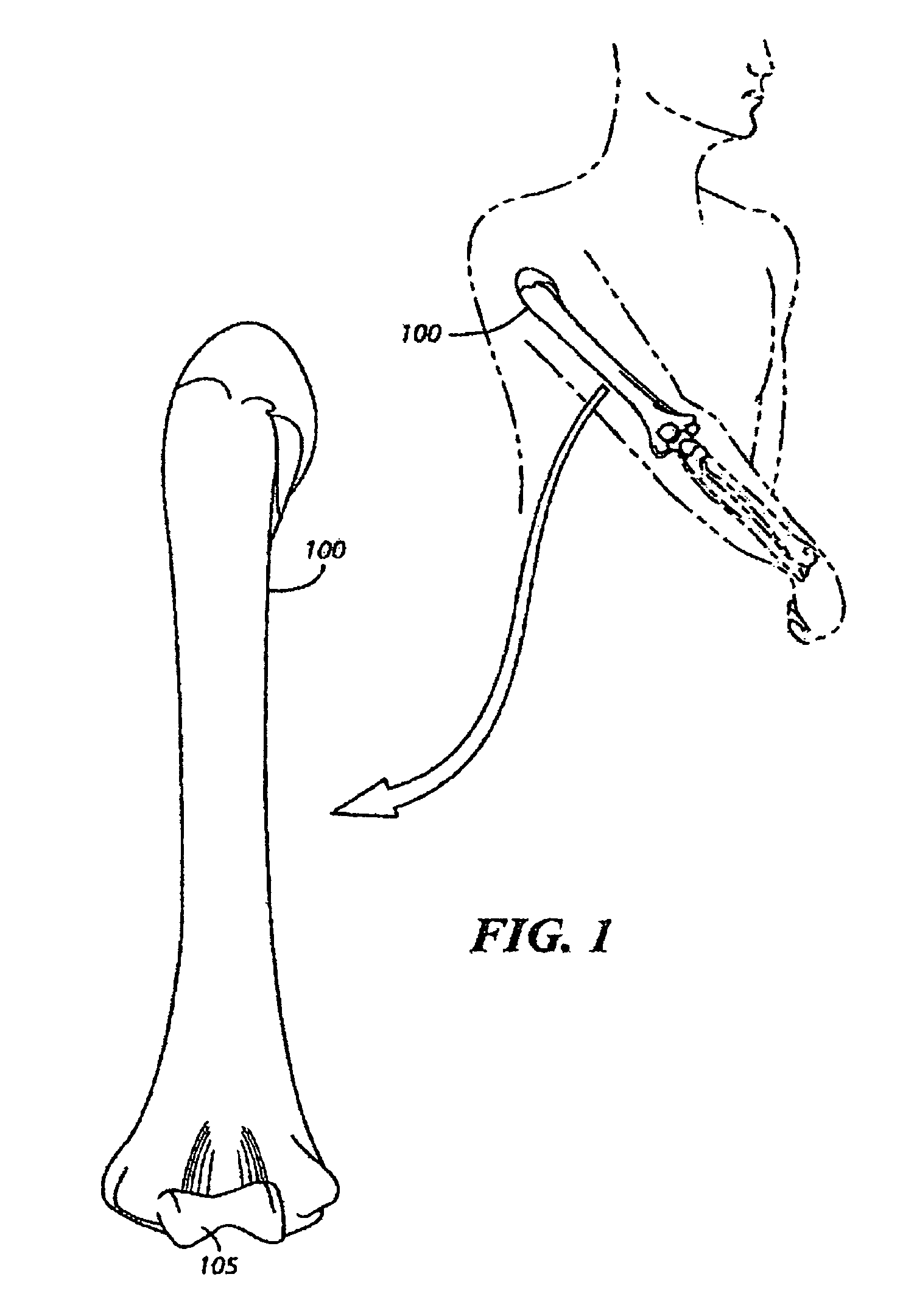
[0029]For purposes of clarity and simplicity, the fracture fixation system of the present invention will be described and illustrated in conjunction with a fractured humerus bone 100. As such, FIG. 1 depicts a rear view of the humerus bone 100 alongside a human figure for perspective. It will be appreciated by those skilled in the art, however, that the fracture fixation system is by no means limited to the support and treatment of the humerus bone 100 and may be adapted to any of a wide variety of other situations without departing from the present invention.

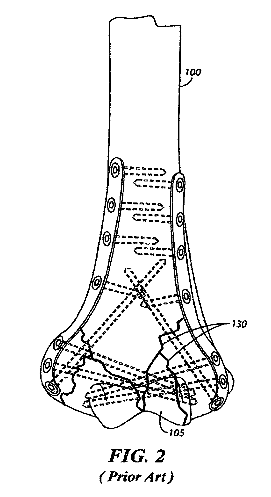
[0030]FIG. 2 shows a fractured humerus bone 100 in conjunction with a typical prior art plate and screw support structure. In this figure, it is seen that the humerus bone 100 has multiple fracture lines 130 in the distal end 140 and is supported ex...


PUM


Abstract

A bone fracture fixation system configured towards the treatment of a variety of different human bone fractures. The fracture fixation system including a plate portion configured to abut bone structure and having a plurality of threaded apertures designed to matingly receive a plurality of screws therein. The bone fracture fixation system will also include at least one scaffold building screw configured to extend through the plate portion and into the bone structure. The scaffold building screw will be configured to include any of a number of different configurations of bracing pegs and / or bracing screws therein to provide substantial structural integrity to the system.

Description

CROSS-REFERENCE TO RELATED APPLICATIONS[0001]This application is a continuation of U.S. Non-Provisional patent application Ser. No. 10 / 993,723, filed on Nov. 19, 2004, (now abandoned); which claims the benefit of Provisional Patent Application Ser. No. 60 / 552,632, filed on Mar. 12, 2004; Provisional Patent Application Ser. No. 60 / 541,540, filed on Feb. 3, 2004; and Provisional Patent Application Ser. No. 60 / 523,960, filed on Nov. 21, 2003; each of which is incorporated herein in its entirety.BACKGROUND OF THE INVENTION[0002]1. Field of the Invention[0003]The present invention relates generally to medical devices configured towards the treatment of bone fractures, and more particularly, to a multi-faceted bone fixation system configured towards treating a variety of different human bone fractures.[0004]2. Description of the Prior Art[0005]A wide variety of devices have been developed for the support and treatment of different bone fractures. Existing solutions have ranged from simpli...

Claims


Application Information

Patent Timeline
Patent Type & Authority Patents(United States)
IPC IPC(8): A61B17/56
CPCA61B17/72A61B17/8061A61B17/68A61B17/7241A61B17/80
Inventor GONZALEZ-HERNANDEZ, EDUARDO
Owner TOBY ORTHOPAEDICS
Why Eureka
Try Eureka