Shutter device and drive method
a drive method and shutter technology, applied in the field of shutter devices, can solve the problems of increasing cost and increasing the number of parts, and achieve the effects of low cost, high space saving, and low number of parts
- Summary
- Abstract
- Description
- Claims
- Application Information
AI Technical Summary
Benefits of technology
Problems solved by technology
Method used
Image

Examples
first embodiment
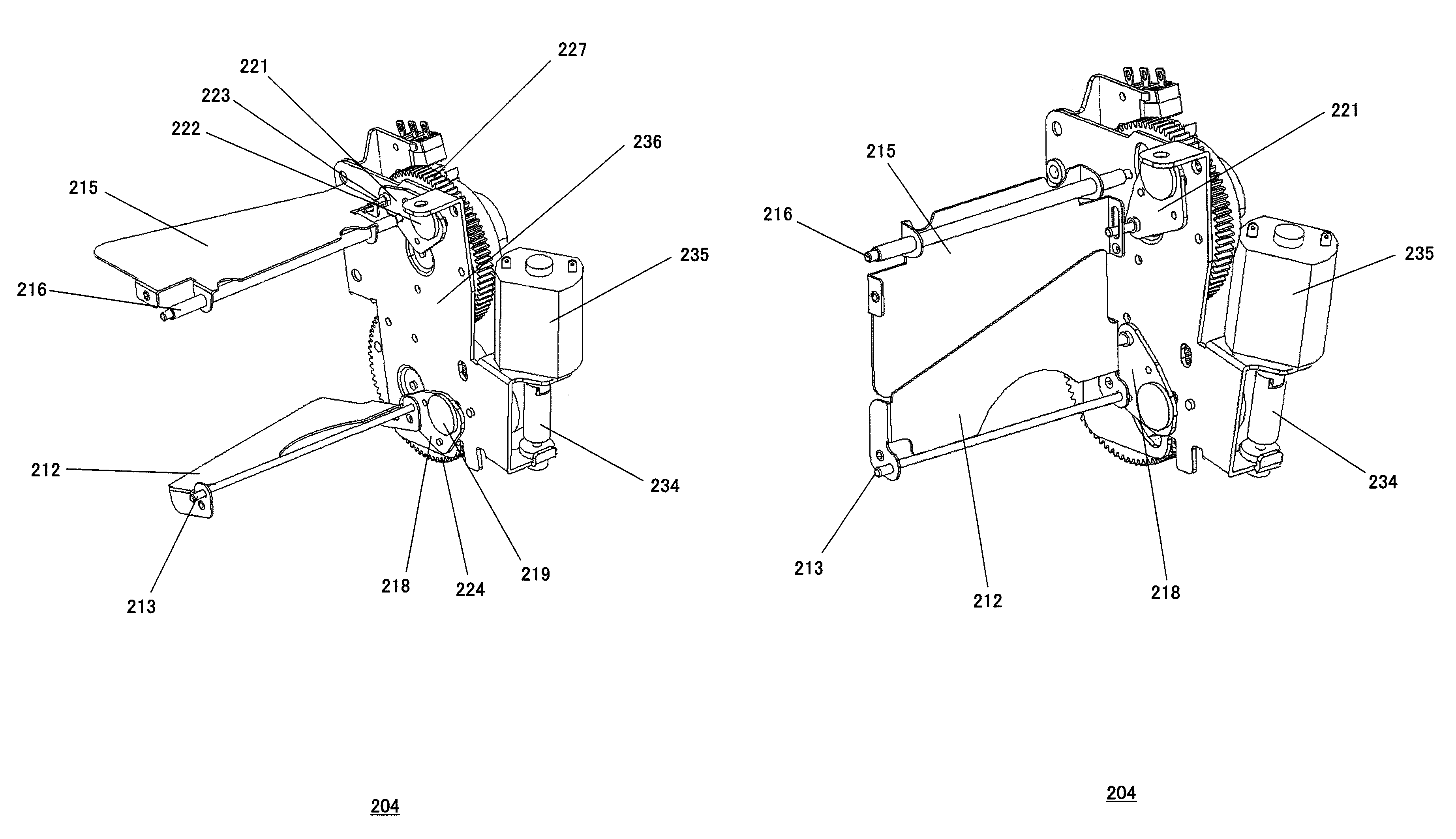
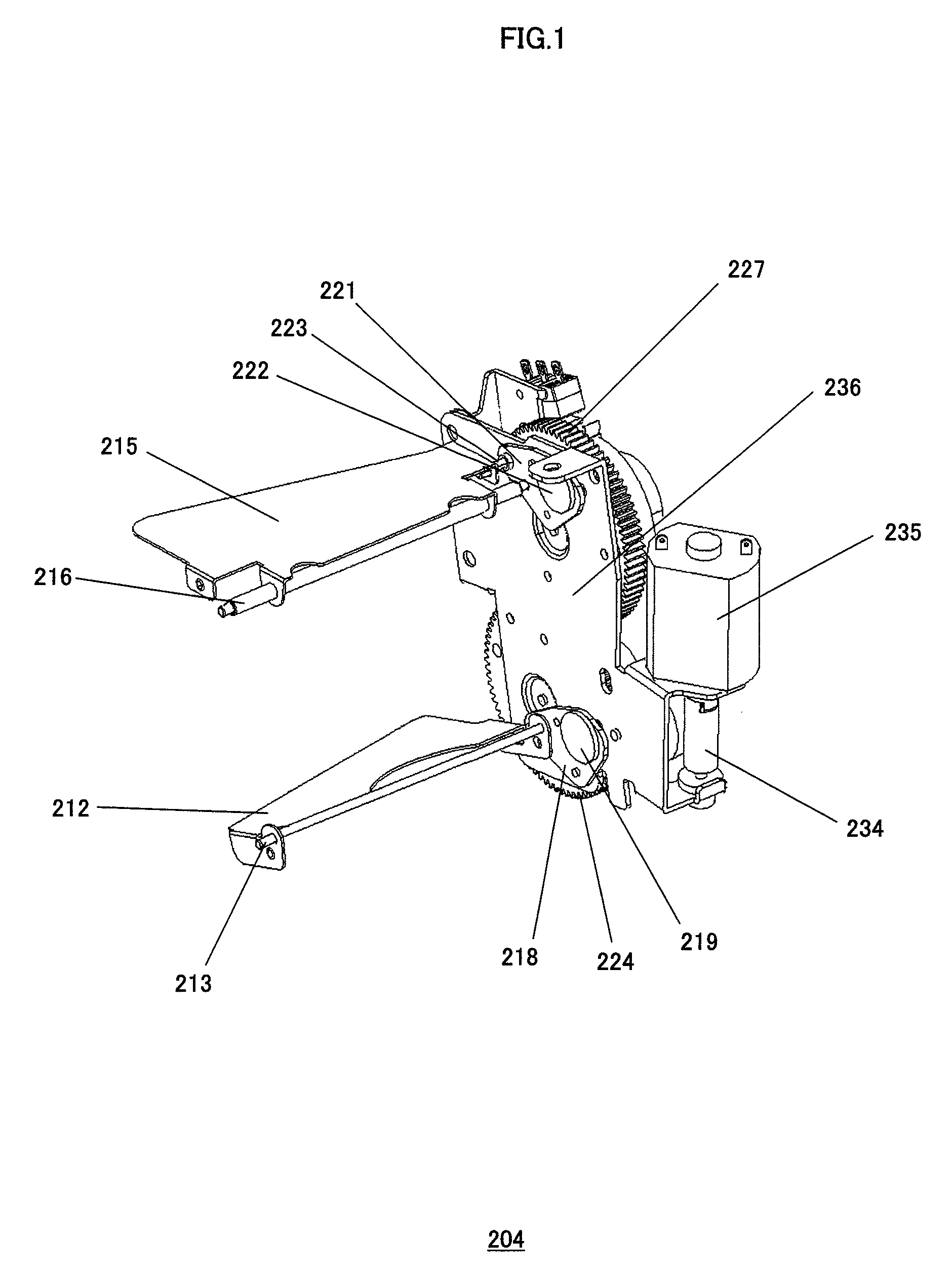
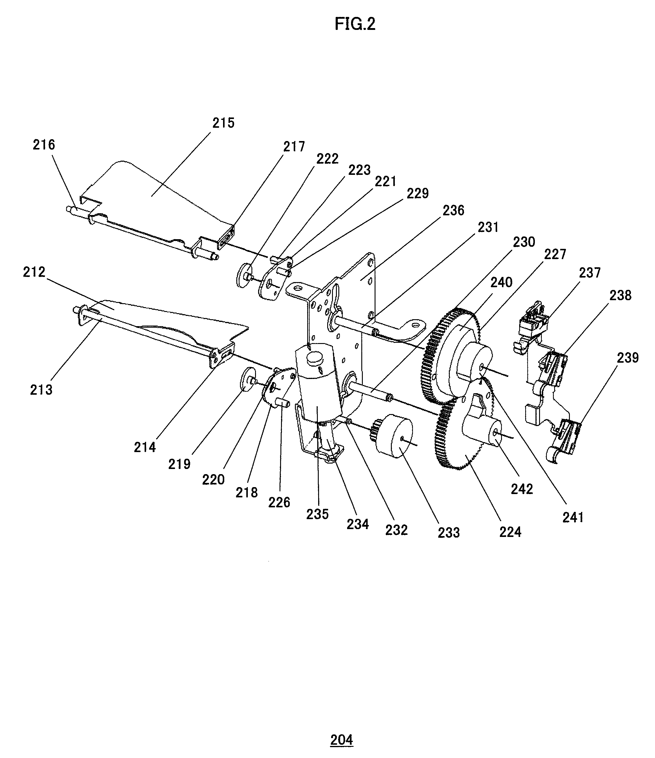
[0104]FIG. 1 to FIG. 4 illustrate a shutter apparatus of the first embodiment of the present invention. FIG. 1 is a perspective view (in usual usage state) illustrating a structure of the same shutter apparatus. FIGS. 2 and 3 are exploded views of the same shutter apparatus. FIG. 4 is a side view showing a sketch of an optical system of a projection display apparatus including the same shutter apparatus. FIG. 5 is a perspective view showing a sketch of the shutter apparatus of the first embodiment of the present invention. FIGS. 6 to 8 are operational explanatory views of the shutter apparatus. FIG. 9 is a perspective view illustrating a structure of the same shutter apparatus in the high contrast state. FIG. 10 is a perspective view illustrating a structure of the same shutter apparatus in the image mute state.
[0105]1. Projection Display Apparatus
[0106]In FIG. 4, a projection display apparatus is composed of a DMD (Digital Micromirror Device) 201, a projection lens 202, an illumina...
second embodiment
[0186]FIG. 11 is a perspective view illustrating the structure of the shutter apparatus of the second embodiment of the present invention in the usual usage state. FIG. 12 is a perspective view illustrating the structure of the same shutter apparatus in the high contrast state. FIG. 13 is a perspective view illustrating the structure of the same shutter apparatus in the image mute state.
[0187]Through FIG. 11 to FIG. 13, same references are used for components which are the same as components in FIG. 1 to FIG. 10 and the description is omitted.
[0188]Through FIG. 11 to FIG. 13, a first shading plate 301, which is mounted on the first rotationally moving pivot 213 so as to be capable of moving rotationally, is formed into the shape that divides the optical path substantially in two. Although the shape of the first shading plate 301 is a kind of shape that intercepts a part of a particular position of the optical path, the surface area that intercepts the optical path is slightly reduce...
third embodiment
[0195]FIG. 14 is a schematic view illustrating the structure of the shutter apparatus of the third embodiment of the present invention in the usual usage state. FIG. 15 is a schematic view illustrating the same shutter apparatus in the high contrast state. FIG. 16 is a schematic view illustrating the structure of the same shutter apparatus in the image mute state. FIG. 17A, FIG. 17B and FIG. 17C are schematic views illustrating positional relation of the position detecting sensors of the same shutter apparatus in each state.
[0196]From FIG. 14 to FIG. 17A, FIG. 17B and FIG. 17C, same references are used for components which are the same as the components in FIG. 1 to FIG. 9 and the descriptions are omitted.
[0197]Through FIG. 14 to FIG. 17A, FIG. 17B and FIG. 17C, the first drive lever 218 and the second drive lever 221 are driven to rotationally move by a first guide member 405 and a second guide member 406 which are fixed, via connecting members 402, 403 and 404, to a rack 401 (corr...
PUM
 Abstract
Description
Claims
Application Information
 - R&D Engineer
- R&D Manager
- IP Professional
- Industry Leading Data Capabilities
- Powerful AI technology
- Patent DNA Extraction
Browse by: Latest US Patents, China's latest patents, Technical Efficacy Thesaurus, Application Domain, Technology Topic.
© 2024 PatSnap. All rights reserved.Legal|Privacy policy|Modern Slavery Act Transparency Statement|Sitemap