Securing device and method for fixing an electric machine to a component

a technology for fixing devices and electric machines, which is applied in the direction of electrical equipment, dynamo-electric machines, supports/enclosements/casings, etc., can solve the problem of not being able to guarantee that the precise positioning remains permanent, and achieve the effect of simple and precis

Active Publication Date: 2017-12-05
ROBERT BOSCH GMBH
View PDF11 Cites 1 Cited by
  • Summary
  • Abstract
  • Description
  • Claims
  • Application Information

AI Technical Summary

Benefits of technology

[0003]The fastening plate in accordance with the invention and the fastening device and also the method for fastening an electric machine have in contrast thereto the advantage that by virtue of embodying a fastening plate with a central receiving opening for the axial extension of the bearing shield of the electric motor it is also possible to compensate effectively for bearing tolerances even over a large temperature range. For this purpose, the receiving opening is formed in the shape of a polygon that is pressed with its lateral surfaces in a radial manner against the axial extension of the electric machine. It is possible using the fastening orifices that are formed on the fastening plate to permanently fasten the electric machine in a highly space saving manner directly on a motor vehicle component.
[0008]In order to embody the lateral walls in such a manner that they move radially, the connecting pieces comprise a radial width of 0.5 mm to 3.0 mm, wherein a width of approx. 1.0 mm has proven itself to be particularly favorable. The axial thickness of the fastening plate in the region of the connecting pieces is ideally likewise 0.5 to 3.0 mm, preferably approx. 1.0 mm. It is possible by virtue of the radially flexibly lateral walls of the receiving opening to achieve a press-fit with the bearing sleeve without having to influence the bearing body inside the bearing sleeve with external press-down forces. The radial movability of the connecting pieces can be achieved in particular in a simple manner by means of elongated slots in the fastening plate, the extension of said slots in the tangential direction being greater than their radial dimension, and said slots being aligned approximately along the straight lateral surfaces.
[0011]The fastening plate is part of a fastening device wherein the fastening plate is fastened in a non-rotatable manner to the bearing sleeve of the electric machine. The bearing sleeve is embodied in one piece with a bearing lid that closes a cylindrical pole housing of the electric machine. The bearing sleeve receives inside a bearing body in which the output shaft of the electric machine is mounted, said output shaft being in particular identical to the rotor shaft of the electric machine. In the case of this fastening device, a roller bearing—by way of example a ball bearing—can be received inside the bearing sleeve in such a manner that the outer bearing ring of the roller bearing is not adversely affected as the fastening plate is pressed onto the bearing sleeve.
[0012]Manufacturing tolerances and also thermal expansions during operation are effectively compensated for by virtue of the fastening method in accordance with the invention by means of the peripheral wall of the through-going orifice deforming in the radial direction. As a result of the symmetrical arrangement of the orifice regions of the lateral walls, the output pinion always remains precisely centered with respect to the fastening orifices. This ensures that the electric machine is positioned in a simple and precise manner during all operating states of the electric machine in the motor vehicle.
[0013]It is possible using this fastening device to fasten by way of example an electric machine that is embodied as a geared drive unit for an adjusting device to the motor vehicle in a reliable manner. By way of example, it is possible using the fastening plate to fasten a seat-adjusting drive, a window-operating drive, a windscreen washer drive or a throttle flap adjuster in the engine compartment to the bodywork in a reliable manner.

Problems solved by technology

However, it is not possible to guarantee that the precise positioning remains permanent particularly if the environmental temperatures change.

Method used


Image

  • Securing device and method for fixing an electric machine to a component
  • Securing device and method for fixing an electric machine to a component
  • Securing device and method for fixing an electric machine to a component

Examples


Embodiment Construction

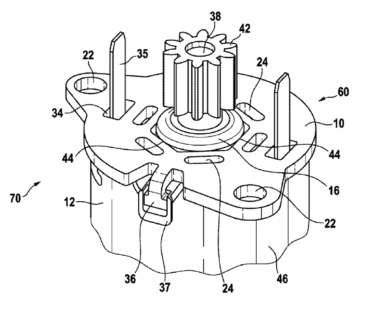
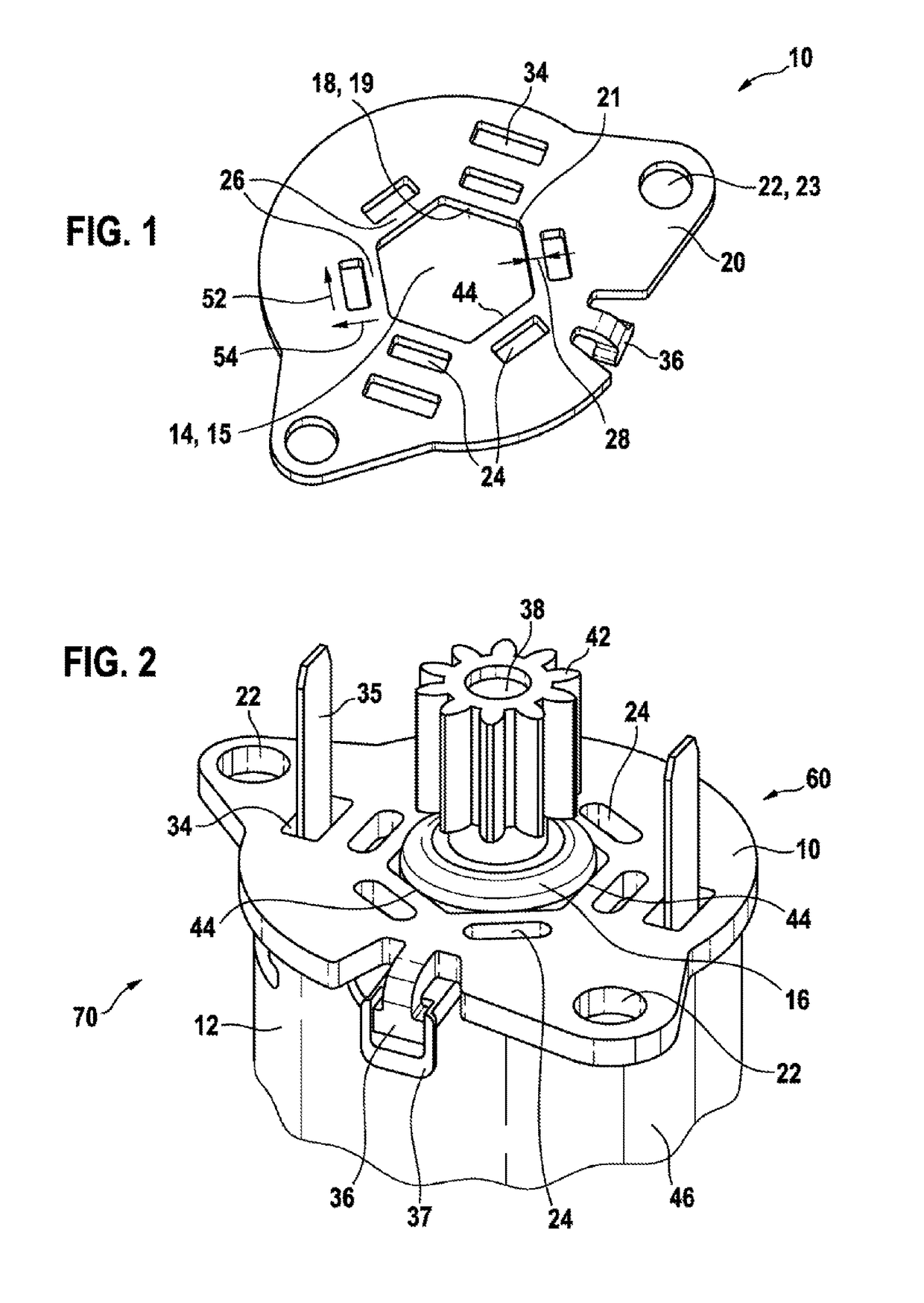
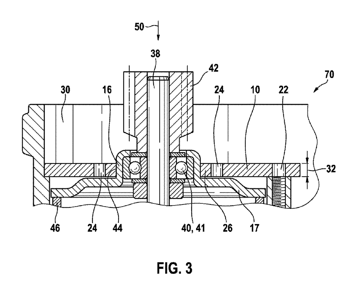
[0019]FIG. 1 illustrates a fastening plate 10 that is suitable for fastening an electric machine 12 to a component 30, by way of example to a motor vehicle bodywork. The fastening plate 10 comprises centrally a through-going orifice 14 into which it is possible to insert an axial extension of the electric machine 12. The through-going orifice 14 comprises planar lateral surfaces 18 that lie against the axial extension in a radial manner after assembly, said extension being embodied by way of example as a bearing sleeve 16. The individual lateral surfaces 18 are mutually connected by way of more or less emphasized corners 21. Consequently, the through-going orifice 14 is embodied approximately as a polygon or polygonal traverse that comprise by way of example rounded corners 21. In FIG. 1, the polygon is embodied by way of example as a hexagon with six planar surfaces 19. However, alternatively, the through-going orifice 14 can also be embodied as a triangle, rectangle, or pentagon. ...


PUM


Abstract

The invention relates to a securing plate (10), a fixing device and to a method for fixing an electric machine (12), for example to a component (30) of a motor vehicle, comprising a central through-opening (14) for receiving a round bearing sleeve (16) of the electric machine (12), said through opening (14) having a polygonal shape (15), the lateral surfaces (18) resting on the bearing sleeve (16). The securing plate (10) has, in a radially outer region (20), securing holes (22) via which the electric machine (12) can be secured to the component (30).

Description

BACKGROUND OF THE INVENTION[0001]The invention relates to a fastening plate, a fastening device, and also a method for fixing an electric machine to a component.[0002]DE 10 2005 030 218 A1 discloses a fastening device, wherein an adapter element is arranged about an output shaft of an electric motor in order to fasten said electric motor by way of example in an automobile bodywork. The adaptor element that is embodied in two pieces is joined in a radial manner to an axial extension of the electric motor. The axial extension is a component of a bearing shield and comprises in its radial outer periphery a form closure that prevents the adapter element from rotating with respect to the electric motor. In order to position the output shaft of the electric motor precisely with respect to the automobile bodywork, very high demands are placed on the production of the adapter element. However, it is not possible to guarantee that the precise positioning remains permanent particularly if the...

Claims


Application Information

Patent Timeline
Patent Type & Authority Patents(United States)
IPC IPC(8): H02K5/22H02K7/116H02K5/04H02K5/15
CPCH02K5/22H02K5/04H02K7/116H02K5/15H02K5/225
Inventor BAUER, BERTRAM
Owner ROBERT BOSCH GMBH
Why Eureka
Try Eureka