Cross-axis joint for a vehicle

a cross-axis joint and vehicle technology, applied in the direction of pivots, shafts and bearings, couplings, etc., can solve the problems of difficult control, difficult to fit the joint or its outer sleeve into the bearing eye, adversely affecting the comfort of the suspension, etc., to reduce the effect of appreciable overlap, prevent dirt and water penetration to the inside of the sleeve joint, and good seal

Active Publication Date: 2013-11-07
ZF FRIEDRICHSHAFEN AG
View PDF17 Cites 6 Cited by
  • Summary
  • Abstract
  • Description
  • Claims
  • Application Information

AI Technical Summary

Benefits of technology

[0005]Accordingly, one objective is to provide a joint design which can be produced inexpensively and can reduce the above-mentioned problems. In particular, the press fitting of the joint into a bearing eye should have no, or only little effect on the fitting of the ball sleeve, but must nevertheless be able to ensure a secure fixing of the joint in the axial direction. Preferably, the outer sleeve should be able to compensate existing tolerances of the press fit and keep the joint characteristics almost constant.

Problems solved by technology

However, the press fitting of the joint or its outer sleeve into a bearing eye often encounters conflicting aims.
Such an increase is often undesired since its result is to impede proper adjustment of the chassis components and hence adversely affect the comfort of the suspension.
Furthermore, such an increase is difficult to control and depends almost only on the diameter tolerances of the components.

Method used


Image

  • Cross-axis joint for a vehicle
  • Cross-axis joint for a vehicle

Examples


Embodiment Construction

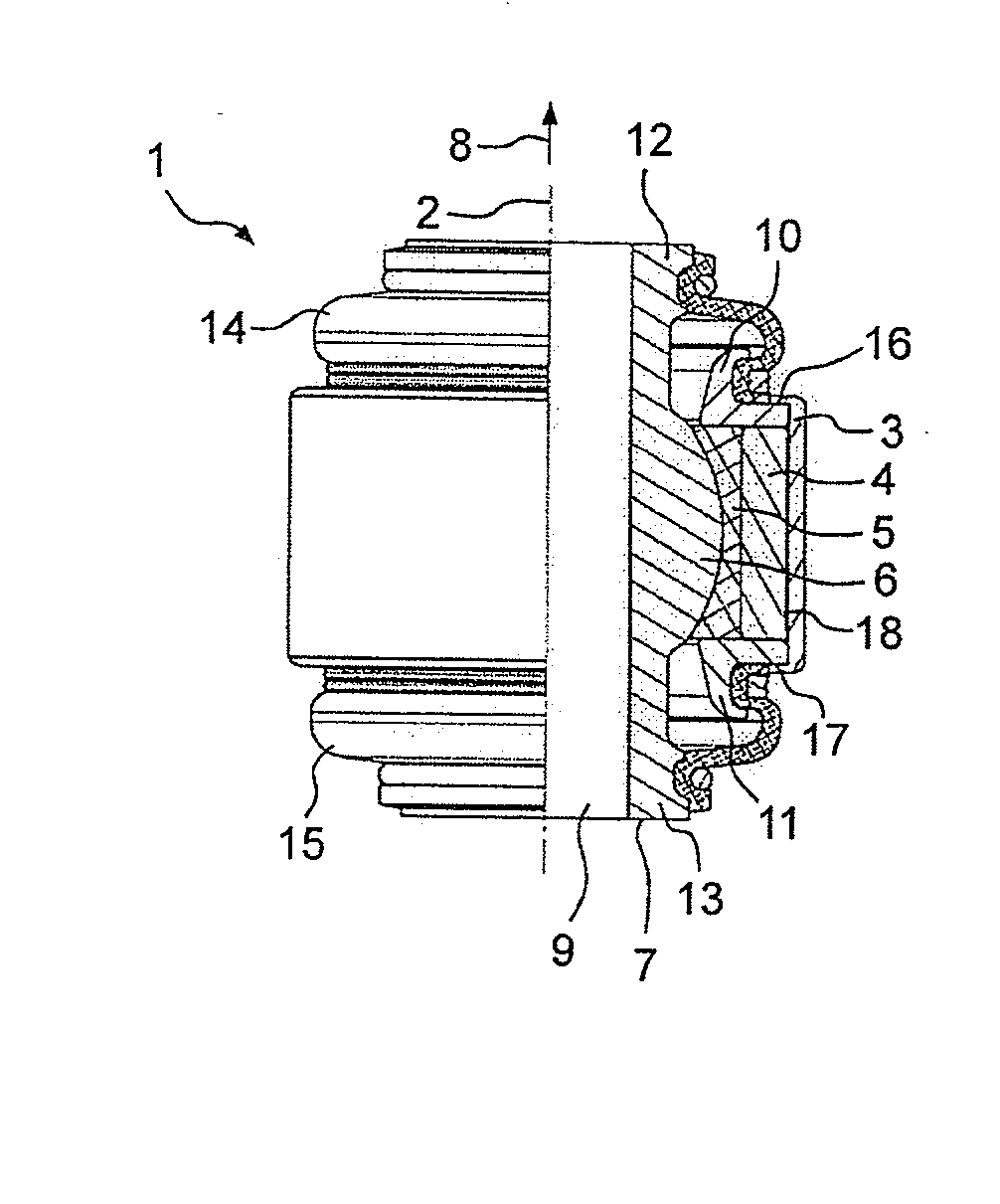
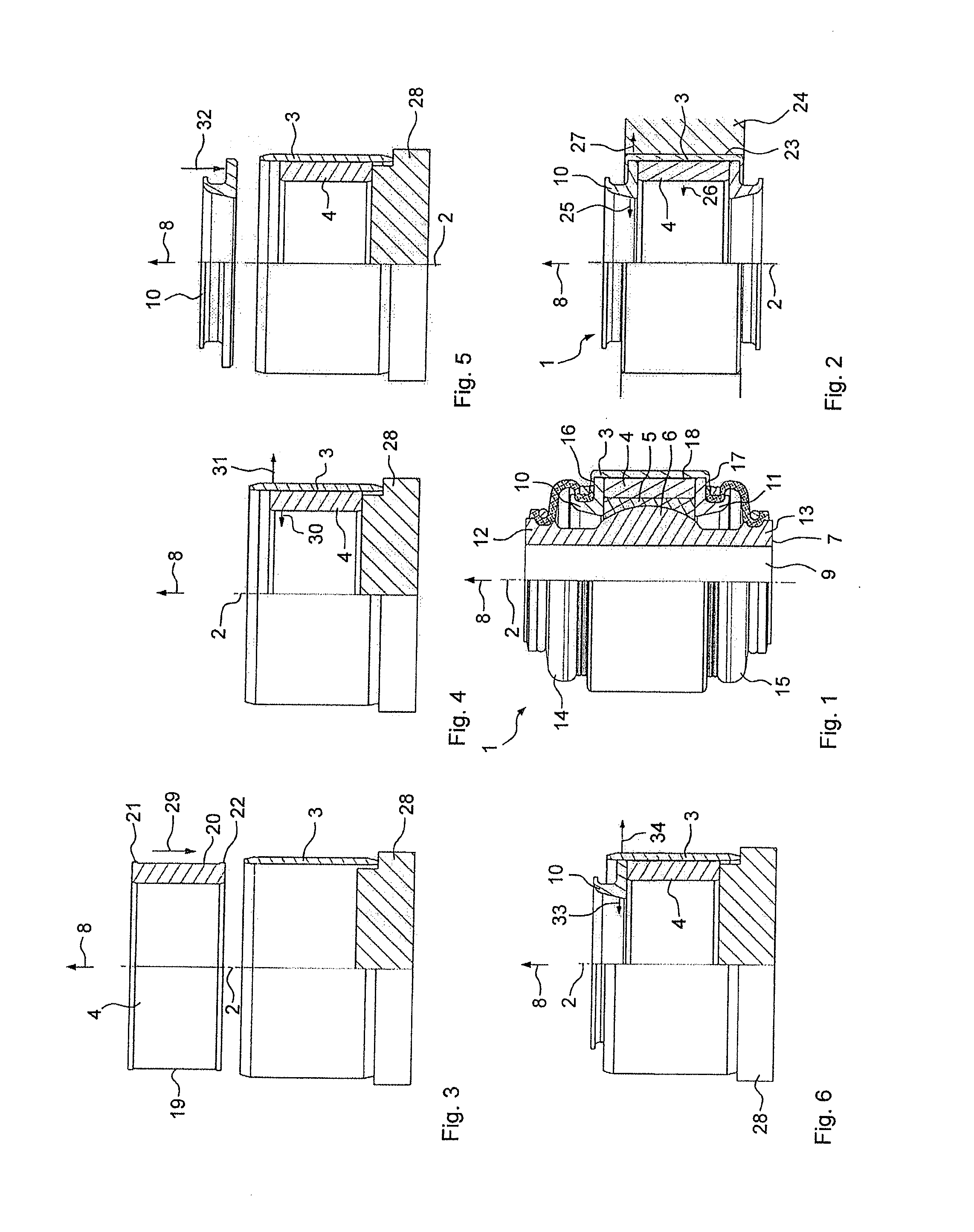
[0041]FIG. 1 shows an embodiment of a sleeve joint 1 which is designed rotationally symmetrical relative to a longitudinal central axis 2 which extends in an axial direction 8. To the left of the longitudinal central axis 2, an outside view of the sleeve joint 1 is shown, whereas in contrast, to the right of the central axis 2, a longitudinal section through the sleeve joint 1 is shown. Into an outer sleeve 3 is inserted an inner sleeve 4, inside which a ball socket 5 is fitted with some radial pre-stress. Inside the ball socket 5 a ball sleeve 7 provided with a joint ball 6 is fitted so that with its joint ball 6 it can rotate and swivel. A through-hole 9 extends all the way through the ball sleeve 7 in the axial direction 8.

[0042]Into the outer sleeve 3 are press-fitted two clamp rings 10 and 11, which rest axially against the ball socket 5 and the inner sleeve 4, which are arranged in the axial direction 8 between the clamp rings 10 and 11 so that the ball socket 5 is under the s...


PUM

PropertyMeasurementUnit
axial lengthaaaaaaaaaa
circumferenceaaaaaaaaaa
diameteraaaaaaaaaa

Abstract

A sleeve joint for a vehicle with an outer sleeve (3) that extends in an axial direction (8). Two clamp rings (10, 11) are arranged inside the outer sleeve (3) and a ball socket (5) is arranged inside the outer sleeve (3). A ball sleeve (7) is fitted in and able to move in the ball socket (5). An inner sleeve (4) is inserted into the outer sleeve (3) and positioned, in the axial direction, between the clamp rings (10, 11) between which the inner sleeve and the ball socket (5) are fitted.

Description

[0001]This application claims priority from German patent application serial no. 10 2012 207 527.5 filed May 7, 2012.FIELD OF THE INVENTION[0002]The invention concerns a sleeve joint for a vehicle, with an outer sleeve that extends in an axial direction, two clamp rings arranged in the outer sleeve, a ball socket arranged in the outer sleeve and a ball sleeve fitted and able to move in the ball socket. In addition the invention concerns a method for producing a sleeve joint, such that in an outer sleeve that extends in an axial direction there are arranged two clamp rings and a ball socket in which a ball sleeve is fitted and able to move.BACKGROUND OF THE INVENTION[0003]A sleeve joint of that type is described for example on page 314 of the Chassis Handbook, Heiβing / Ersoy, 1st Edition 2007, ISBN 978-3-8348-0105-0.[0004]Nowadays sleeve joints are used for various purposes in vehicles and are press-fitted for example into bearing eyes of spring links, wheel carriers or shock absorber...

Claims


Application Information

Patent Timeline
Patent Type & Authority Applications(United States)
IPC IPC(8): F16C11/06
CPCF16C11/0614F16C11/0685Y10T29/4994Y10T403/32737
Inventor BROEKER, KLAUSKLEINEBENNE, MELANIEGUTZLAFF, MARKUS
Owner ZF FRIEDRICHSHAFEN AG
Why Eureka
Try Eureka