X-ray computed tomography apparatus with beam-gating diaphragm

a computed tomography and beam-gating technology, which is applied in the field of x-ray computed tomography apparatuses, can solve the problems of inability to accurately position the absorber element, the absorber element cannot always be precisely produced with the necessary precision, and the carrier warps unexpectedly, so as to achieve the effect of reducing production expenditure, shortening structural height and shortening heigh

Inactive Publication Date: 2006-06-01
SIEMENS AG
View PDF9 Cites 6 Cited by
  • Summary
  • Abstract
  • Description
  • Claims
  • Application Information

AI Technical Summary

Benefits of technology

[0011] In a further embodiment, the absorber element is additionally attached to the projections by means of an adhesive. Such an additional adhesion damps vibrations that may otherwise be conducted by the absorber element.
[0012] In a embodiment, projections are provided on the walls of the groove approximately opposite one another. This enables the carrier to accept either an absorber element with a larger radius or an absorber element with a smaller radius. A separation between the opposite walls of the groove appropriately corresponds to more than double the thickness of the strip. This enables the absorber elements to move atop one another, i.e. in an overlapping position, upon closure of the diaphragm. The thickness of the strip is appropriately in the range from 2.0 to 2.5 mm. In the overlapping state, the absorber elements typically exhibit a gap interval of 0.6 to 1.0 mm. As a result, it is appropriate for the distances between the opposite walls of the groove to be in the range from 4.0 to 6.0 mm. The carrier in this case can be fashioned identical i

Problems solved by technology

Due to the extreme hardness of materials that are composed of tungsten in substantial amounts, a predetermined curvature radius cannot always be produced with the necessary precision in the absorber elements.
When mounting the absorber element on the carrier purely by a positive fit, it may occur th

Method used


Image

  • X-ray computed tomography apparatus with beam-gating diaphragm
  • X-ray computed tomography apparatus with beam-gating diaphragm
  • X-ray computed tomography apparatus with beam-gating diaphragm

Examples


Embodiment Construction

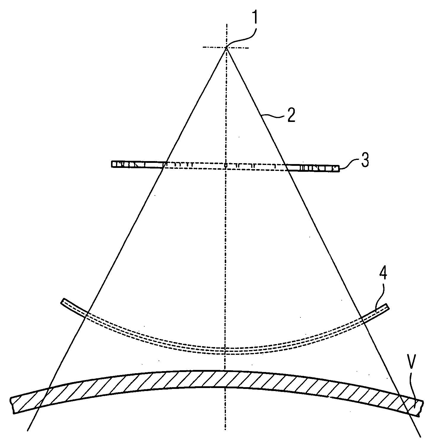
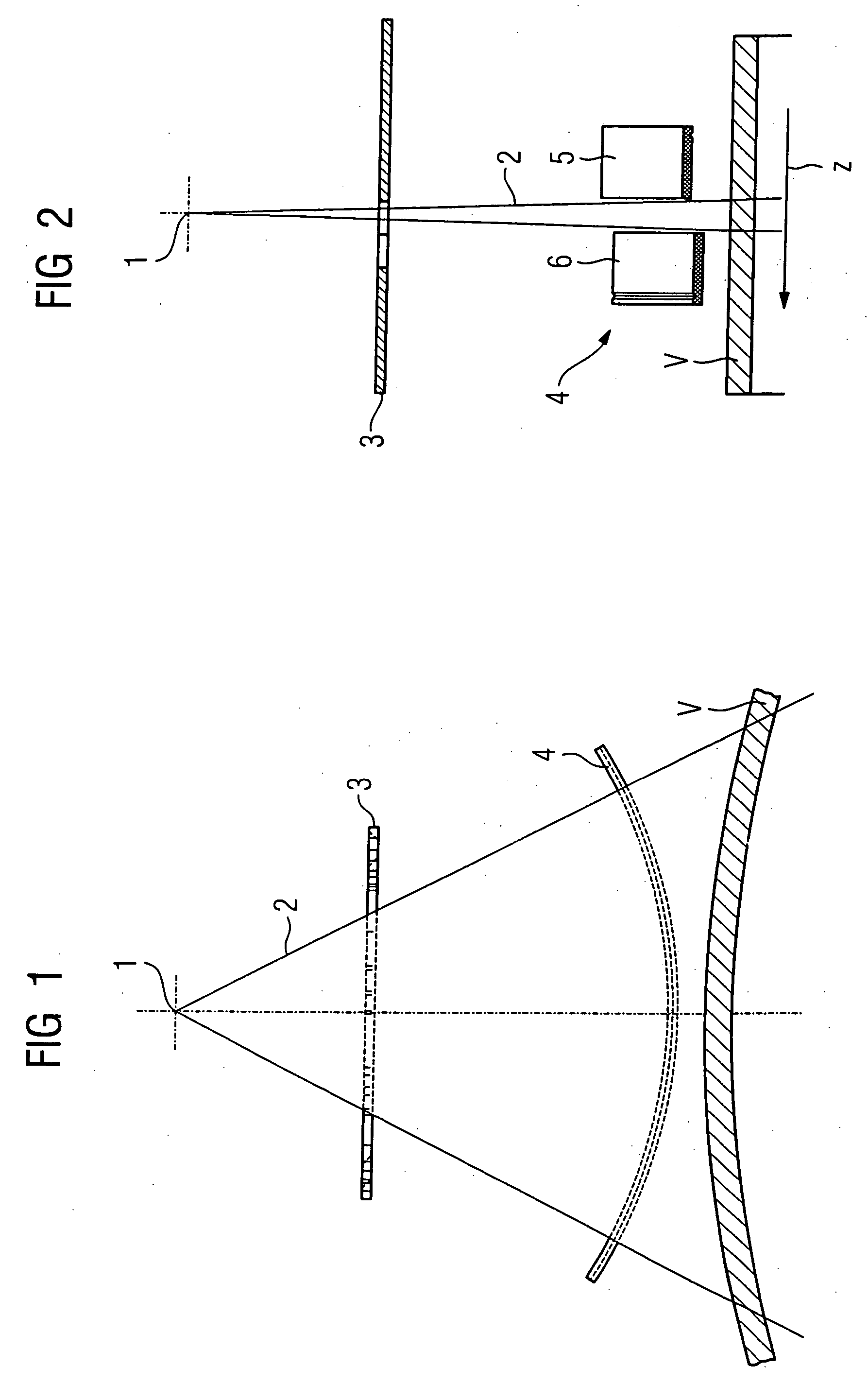
[0025] The x-ray beam path of a computed tomography apparatus is schematically shown in FIGS. 1 and 2. The beam emanated from a focus 1 of an x-ray source (not shown). The fan-shaped x-ray beam 2 originating from the focus 1 is defined in terms of its geometry by a pre-diaphragm 3 and a diaphragm 4 arranged downstream in the beam propagation direction. The enclosure of a patient tunnel of the computed tomography apparatus is designated with the reference character V. The diaphragm 4 is formed of a first gating element 5 and a second gating element 6. The first gating element 5 and the second gating element 6 can be moved toward and away from one another parallel to a z-axis shown in FIG. 2.

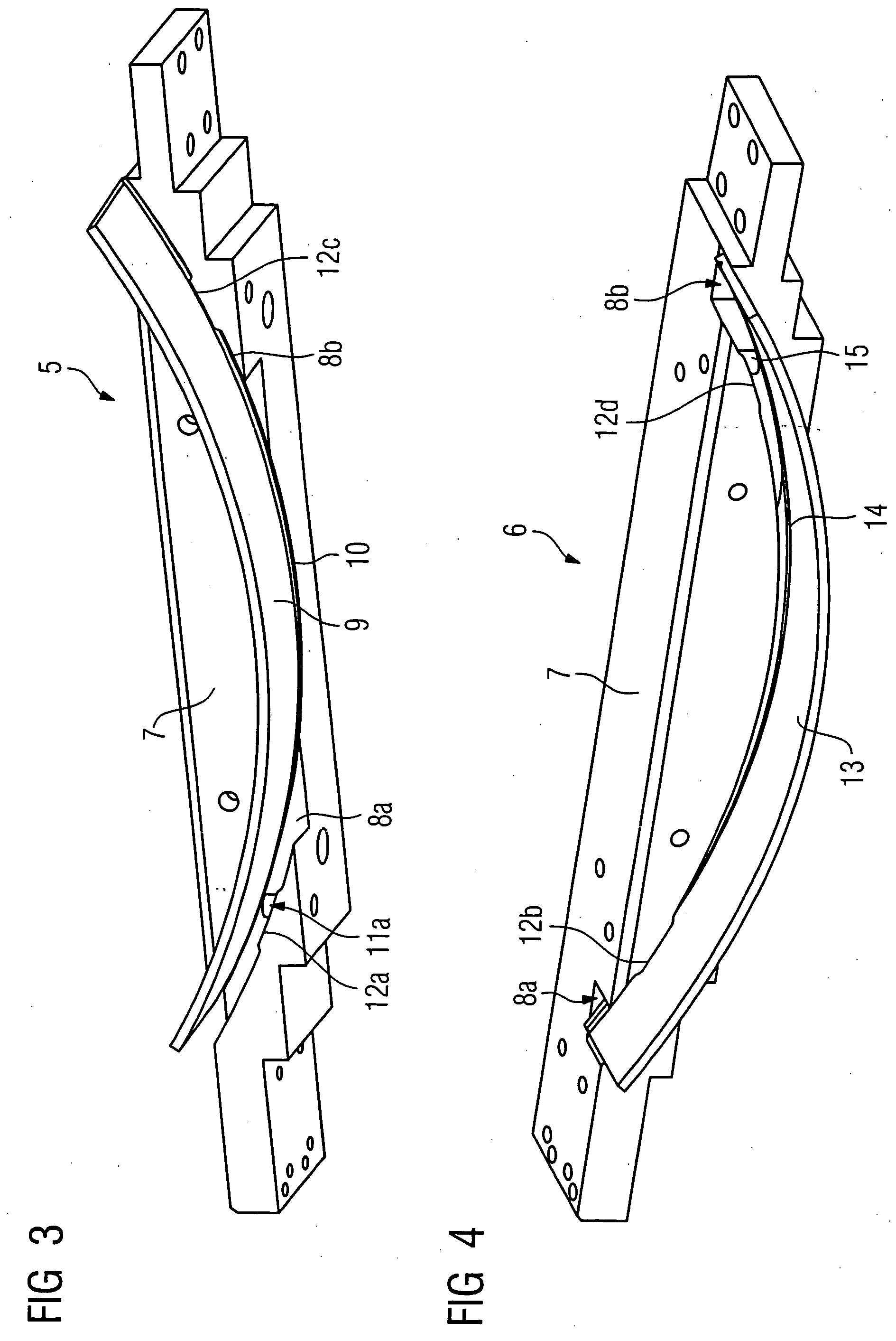
[0026] In the first gating element 5 shown in perspective in FIG. 3, a carrier is provided with a first groove segment 8a and a second groove segment 8b. The opposite inner and outer walls of the groove segments 8a and 8b respectively lie on a common circular arc. A first absorber element 9 is ac...


PUM


Abstract

An x-ray computed tomography apparatus has an x-ray source that can be rotated around a system axis and a diaphragm that is disposed downstream from the x-ray source in the ray propagation direction for gating a fan-shaped ray beam that irradiates a subject. The diaphragm has two gating elements in each of which an absorber element is held, clamped on a carrier at two points in a clamping device provided on the carrier.

Description

BACKGROUND OF THE INVENTION [0001] 1. Field of the Invention [0002] The present invention concerns an x-ray computed tomography apparatus having a beam-gating diaphragm. [0003] 2. Description of the Prior Art [0004] An x-ray computed tomography apparatus of the above general type is known from German OS 102 42 920. Curved absorber elements produced, for example, from tungsten or a tungsten composite material are mounted with a positive fit on a carrier manufactured from aluminum in the diaphragm of this known x-ray computed tomography apparatus. Due to the extreme hardness of materials that are composed of tungsten in substantial amounts, a predetermined curvature radius cannot always be produced with the necessary precision in the absorber elements. When mounting the absorber element on the carrier purely by a positive fit, it may occur that the carrier warps in an unexpected manner. This can lead to the absorber element not being able to be positioned with sufficient precision, an...

Claims


Application Information

Patent Timeline
IPC IPC(8): H05G1/60A61B6/00G01N23/00G21K1/12
CPCA61B6/032A61B6/06G01N23/04G21K1/02
Inventor KUHN, ULRICH
Owner SIEMENS AG
Why Eureka
Try Eureka