Method for producing a device for controlling the flow of a gaseous or liquid medium

a technology of gaseous liquid and flow control, which is applied in the direction of functional valve types, exhaust gas recirculation, fuel addition of non-fuel substances, etc., can solve the problems of large leakage, relatively soft plastic material, and failure to meet the requirements of the intended use of the devi

Inactive Publication Date: 2008-06-26
GUSTAV WAHLER U
View PDF7 Cites 5 Cited by
  • Summary
  • Abstract
  • Description
  • Claims
  • Application Information

AI Technical Summary

Benefits of technology

[0006]It is therefore an object of the invention is to create a method of the type defined at the outset which in a simple, economical way makes it possible to produce a valvelike device with a flap that closes extremely tightly even over a long service life.
[0008]The method according to the invention makes it possible, with a simple, economical procedure, to produce a device that in operation as intended closes extremely tightly whenever the flap is in the closing position. This is also assured without change over quite a long service life of the device. Between the flap and the housing, there is essentially a linear contact. In the embodiment as an exhaust gas recirculation valve, this has the great advantage that a tendency to stick in the closing state because of exhaust gas condensates is avoided. The virtually complete tightness attainable in the closing position of the flap means that in the closing position, there is either no leakage or only extremely small negligible leakage.
[0009]The method has the advantage that in the event of a plastic deformation of the metal housing, at least in the region of a preferably oblique inclined face, and / or of the flap, in its peripheral region, tolerances both for the flap and in the region of the respective stop face of the housing, for instance on the surface, are compensated for. It is also advantageous that a plastic deformation of the housing and / or of the flap occurs only a single time, and thus the respective stop face of the housing and the associated peripheral region of the flap and hence the cooperating contacting surfaces are pressed against one another. The invention thus makes possible the adjustment or even calibration of compensation for tolerances. As a result, there is no need for especially stringent demands in terms of tolerances in the production of the flap and of the stop faces of the housing, since these tolerances are automatically compensated for by the one-time plastic deformation of the housing and / or of the flap. This too results in a cost reduction in the production of both the housing and the flap.
[0010]A device produced by the method of the invention moreover has the advantage that depending on given conditions, the closing force required, in operation as intended, to bring about and maintain the closing position of the flap can be reduced, compared to conventional devices, or as needed even be selected to be greater than the allowable closing force in the known valve of DE 196 03 547 A1, a force that in this known valve, because of the plastic material of the flap, can be only slight so as to avoid permanent deformation.

Problems solved by technology

Such flaps, made of relatively soft plastic material, do not meet the requirements for the intended use of the device.
Because of these flaps, the service life of such devices is relatively short.
Since it cannot be precluded that contaminants or similar particles will be entrained in the medium, these entrained particles can accumulate, in the closing position of the flap, between the peripheral region of the flap and the stop faces of the housing and press into the material comprising the flap or in some other way damage the peripheral region of the flap and involve the stop faces of the housing as well, with the result that relatively quickly, a lack of tightness in the closing position of the flap ensues, resulting in relatively major leakage.
It is also disadvantageous that producing such a device involves difficulties; this is because upon heating and deforming of the plastic flap, care must be taken in its peripheral region that this peripheral region will not flow entirely away, in which case even upon production, the result is a flap that is unusable.
The known method described is therefore unsuitable for the production of such devices, especially valves, of which a long service and durability and at the same an extremely tightly closing flap in the closing position are expected, and all of this is expected to be reliable over a long period of operation.
They are disadvantageous on account of major leakage.
Their disadvantages are either major leakage because of component and assembly tolerances, or very high production costs because of the high precision required.
The disadvantage of these valves are the high opening forces required to overcome the frictional force, and high production costs.

Method used


Image

  • Method for producing a device for controlling the flow of a gaseous or liquid medium
  • Method for producing a device for controlling the flow of a gaseous or liquid medium
  • Method for producing a device for controlling the flow of a gaseous or liquid medium

Examples


Embodiment Construction

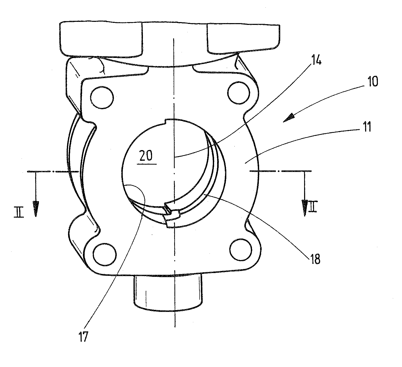
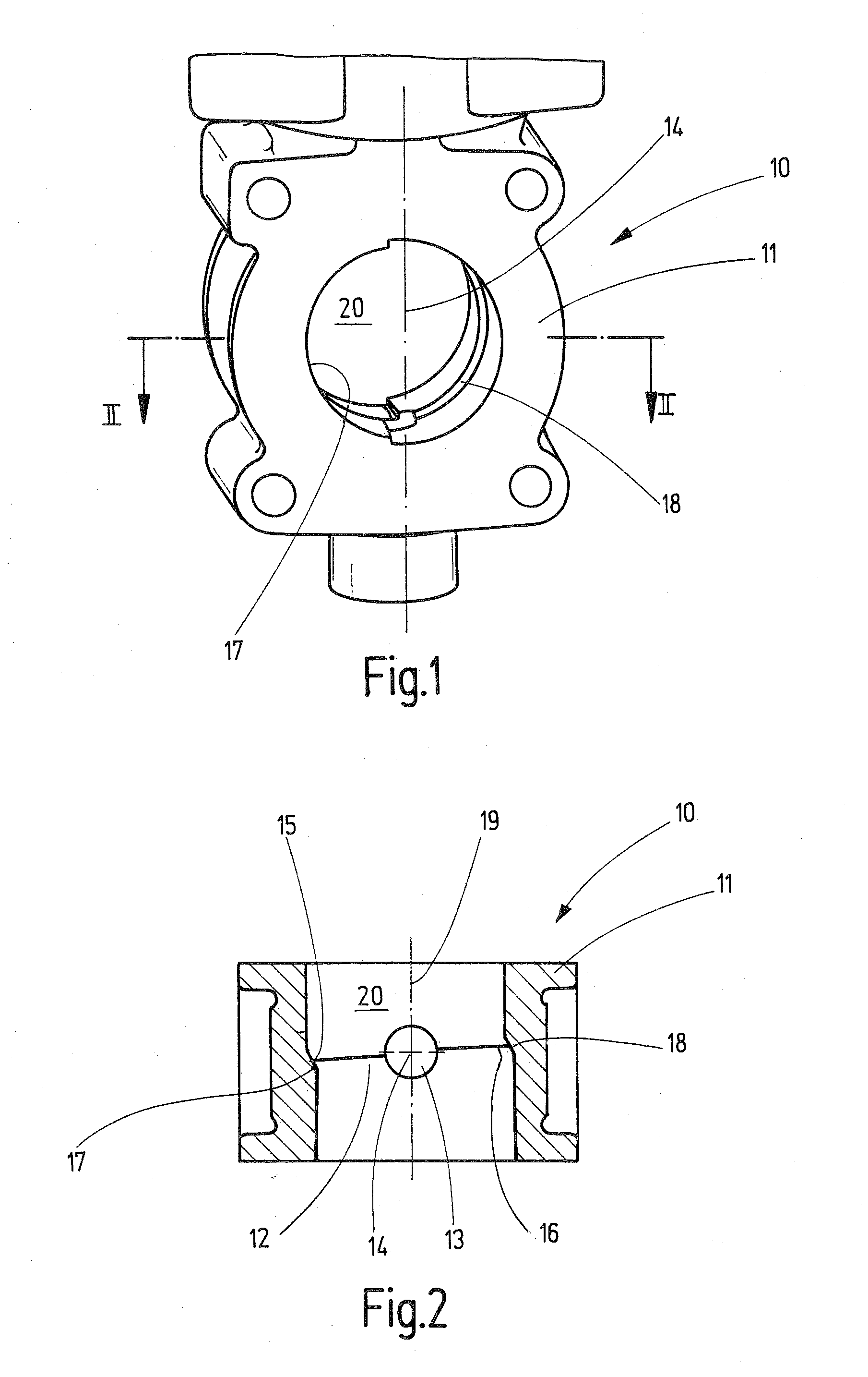
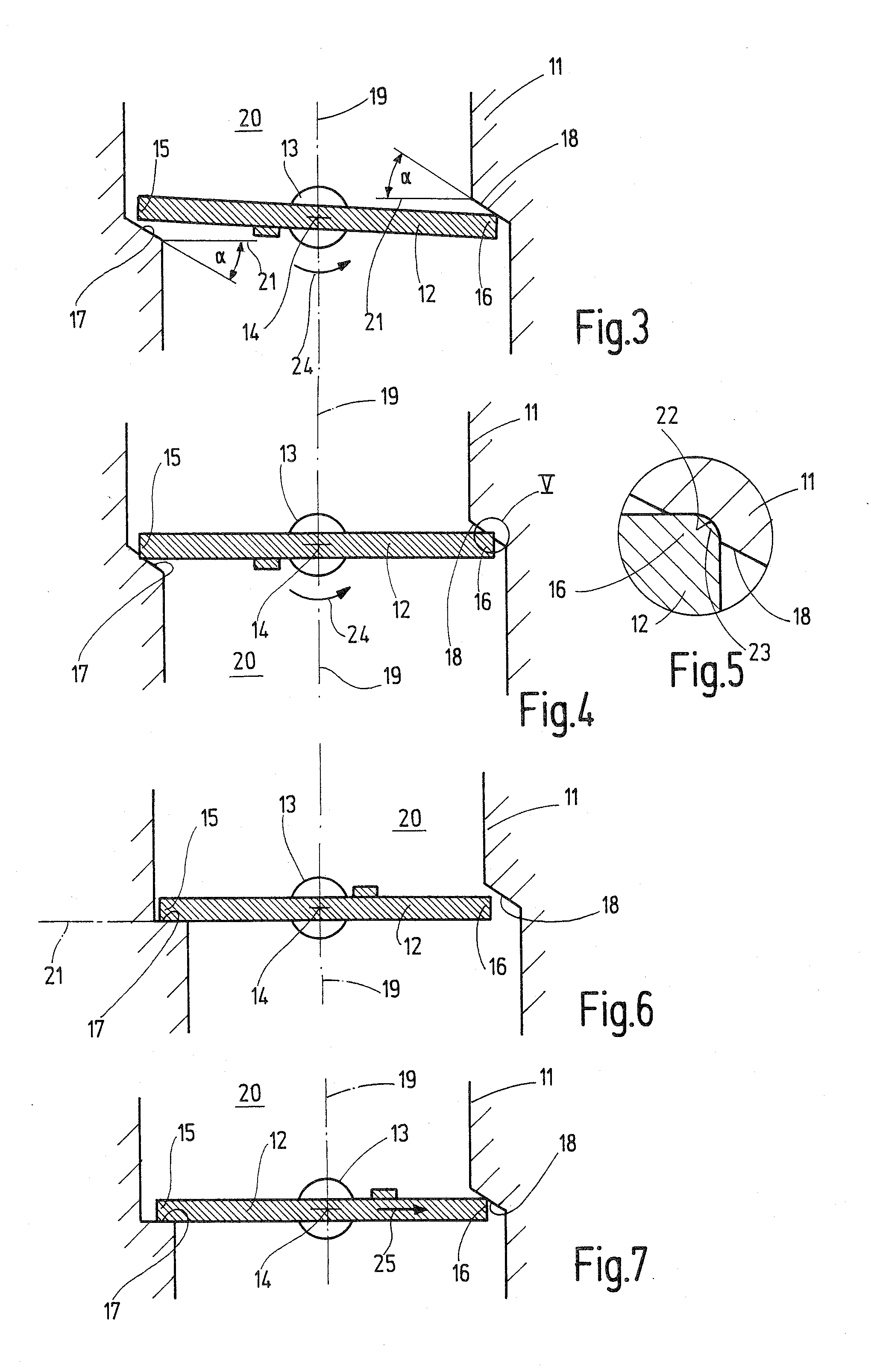
[0020]In FIGS. 1 through 5, a first exemplary embodiment is shown of a device 10 for controlling the flow of a gaseous or liquid medium. The device 10 is an exhaust gas recirculation valve, for example. The device 10 has a housing 11 and in it a valve closure member, embodied here as a flap 12. The flap 12 is secured in or on a flap shaft 13 and is supported pivotably and actuatably about the longitudinal axis 14 between an open position and a closing position, the latter shown in FIG. 2. The flap 12 in the exemplary embodiment shown is approximately circular in shape, but the circumferential contour of the flap 12 may also be designed differently. In the closing position in FIG. 2, the flap 12 rests with peripheral regions 15, 16, present on both sides of the longitudinal axis 14, on associated stop faces 17 and 18, respectively, of the housing 11 that in adaptation to the contour of the flap 12 extend approximately semicircularly. The housing 11 includes a central passage 20 in th...


PUM


Abstract

For producing a device for controlling the flow of a medium, having a housing and a flap supported pivotably in it between a closing position and an open position, which flap in its closing position rests with its peripheral region on stop faces of the housing that are present on both sides of the longitudinal axis, to create tightness in the closing position in later operation, the flap is subjected to a force which is selected, taking into account the material comprising the stop faces and the flap, such that the flap with its peripheral region rests on at least one stop face at least substantially with linear contact. The force can be selected such that the housing, in the region of at least one stop face, and / or the flap, in its peripheral region, is permanently deformed. The housing and the flap are of metal.

Description

CROSS-REFERENCE TO A RELATED APPLICATION[0001]The invention described and claimed hereinbelow is also described in German Patent Application DE 10 2006 060 876.3 filed on Dec. 22, 2006. This German Patent Application, whose subject matter is incorporated here by reference, provides the basis for a claim of priority of invention under 35 U.S.C. 119(a)-(d).BACKGROUND OF THE INVENTION[0002]The invention relates to a method for producing a device for controlling the flow of a gaseous or liquid medium.[0003]In known methods of this type (German Patent Disclosure DE 196 03 547 A1), a plastic flap is heated by means of supplied energy in its closing position and subjected to a closing force such that the peripheral regions of the flap that rest on stop faces of the housing are plastically deformed and thus adapted to the stop faces of the housing. Such flaps, made of relatively soft plastic material, do not meet the requirements for the intended use of the device. Because of these flaps, t...

Claims


Application Information

Patent Timeline
Patent Type & Authority Applications(United States)
IPC IPC(8): F16K17/36
CPCF02D9/107F02M25/0714Y02T10/121F16K27/0218F02M25/0793F02M26/11F02M26/70Y10T137/0753
Inventor WALTER, GERHARDLOHR, MARCUSKRIEGER, BJOERN
Owner GUSTAV WAHLER U
Why Eureka
Try Eureka