Electromagnet for actuating a hydraulic valve

a technology of electric motor and hydraulic valve, which is applied in the direction of electromagnet, valve details, core/yokes, etc., can solve the problems of the inability to adjust the electromagnet with the hydraulic cartridge, and the inability to know the installed throttle, etc., to achieve simple, compact and economical configuration, and reduce the stock of distributing valves of this type. , the effect of easy adjustmen

Inactive Publication Date: 2005-01-11
BOSCH REXROTH AG
View PDF7 Cites 5 Cited by
  • Summary
  • Abstract
  • Description
  • Claims
  • Application Information

AI Technical Summary

Benefits of technology

In contrast, the electromagnet according to the invention for actuating a hydraulic valve has the advantage that it comprises a throttling site that can be adjusted from the outside even after it is installed on a valve, making it possible to subsequently adapt the electromagnet to desired switching speeds without having to remove it. The throttling effect can then be adjusted for fine-tuning directly on the machine on which the distributing valve is mounted. It is also possible to compensate for hydraulic tolerances between individual machines. The adjustable throttling site installed in the armature can therefore be adjusted easily from the outside on the mounted valve. The electromagnet makes a simple, compact and economical configuration possible, and previous parts can be used further without significant changes. Since the throttling site is adjustable, the stockpiles of distributing valves of this type can be reduced, and adjusting effort is minimal. Furthermore, the function of the manual emergency actuation device is retained, and the two functions of manual emergency actuation and adjustment of switching speed can be integrated in the electromagnet in favorable fashion.

Problems solved by technology

As a result, the solenoid armature is housed in a closed space of the “pressure tube” and is unaccessible after assembly.
The disadvantage of this is the fact that a customer can only order a valve having a specified throttle diameter, and he does not know if the installed throttle meets the desired requirements until a machine is operated.
Although the damping can be adjusted here using a throttle screw in the hydraulic cartridge that is accessible from the outside after the electromagnet and / or the solenoid valve are installed on a machine, the electromagnet with hydraulic cartridge is extremely costly to build with an additional piston-cylinder unit with spring and a rolling membrane for delimiting the space filled with hydraulic fluid, making it unusable in many cases for reasons of cost and space.

Method used


Image

  • Electromagnet for actuating a hydraulic valve
  • Electromagnet for actuating a hydraulic valve
  • Electromagnet for actuating a hydraulic valve

Examples


Embodiment Construction

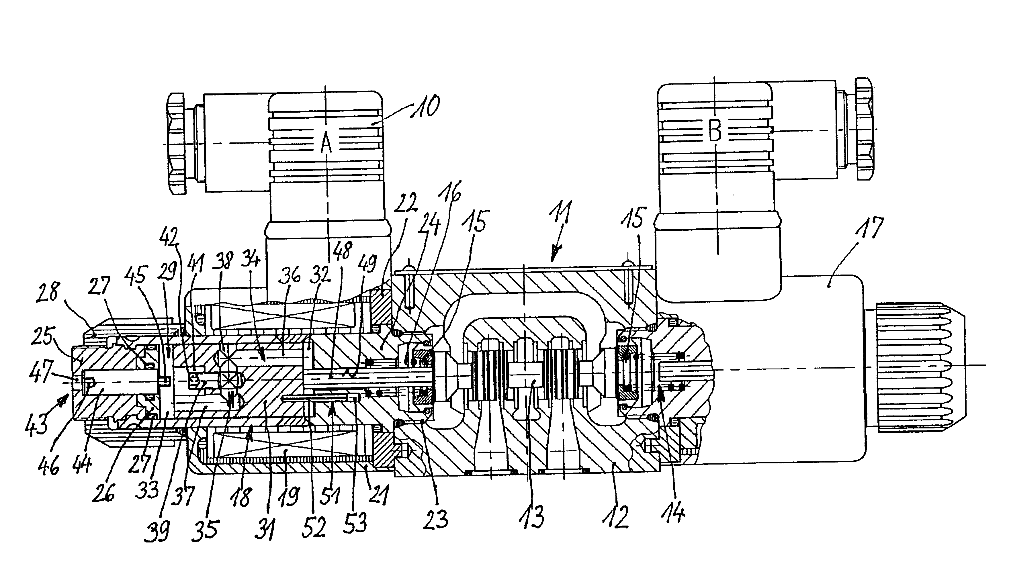
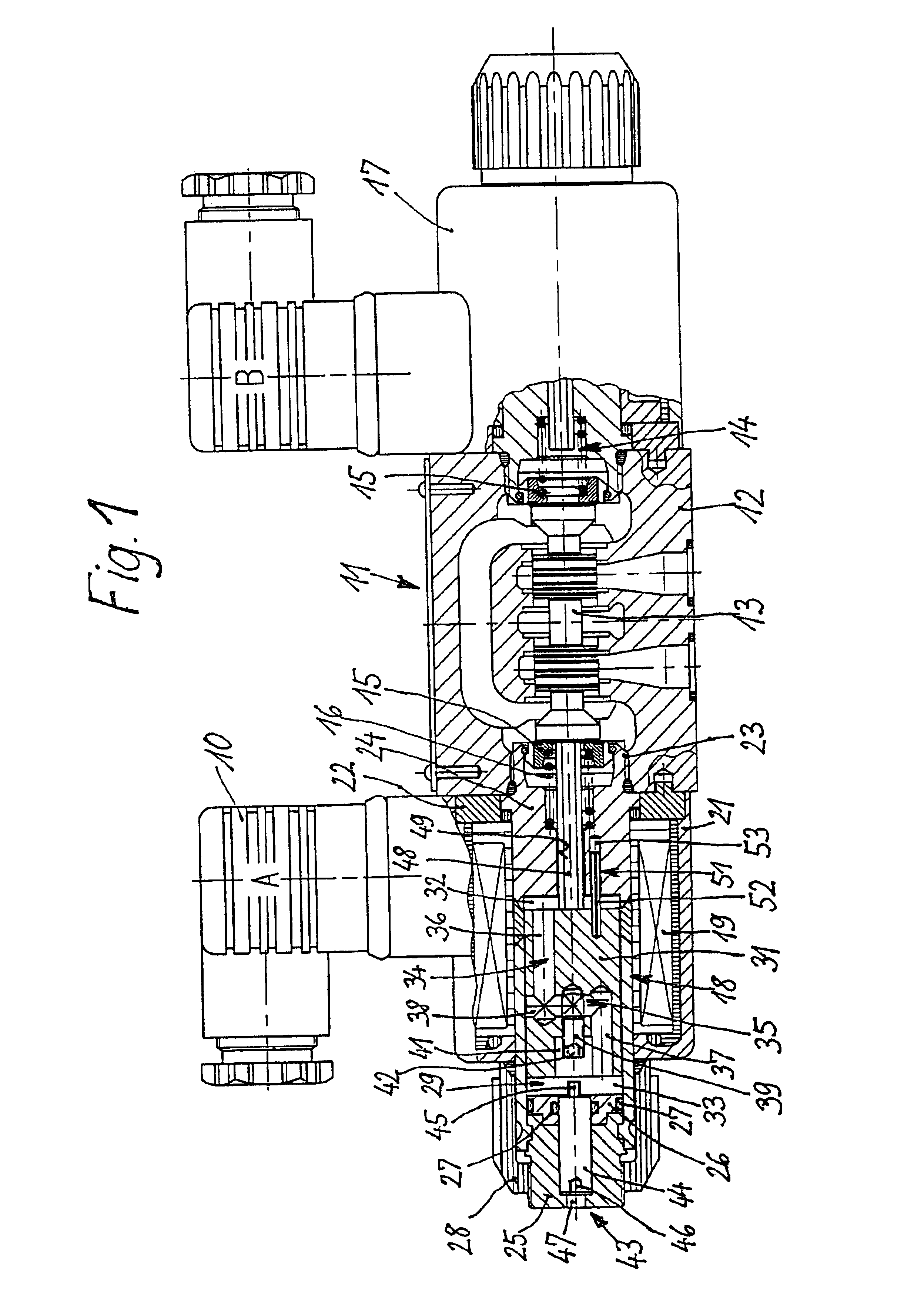
FIG. 1 shows a simplified longitudinal sectional drawing through an electromagnet 10 for actuating a hydraulic valve that is designed here as a standard 4 / 3-distributing valve 11. The distributing valve 11 accommodates a valve spool 13 in a valve housing 12, which said valve spool is centered in the central position shown in the drawing by means of a double-acting return mechanism 14 with spring seats 15 and return springs 16. From said central position, the valve spool 13 can be deflected to either side into working positions, and a second electromagnet 17 having an identical configuration is located on the valve housing 12 for this purpose.

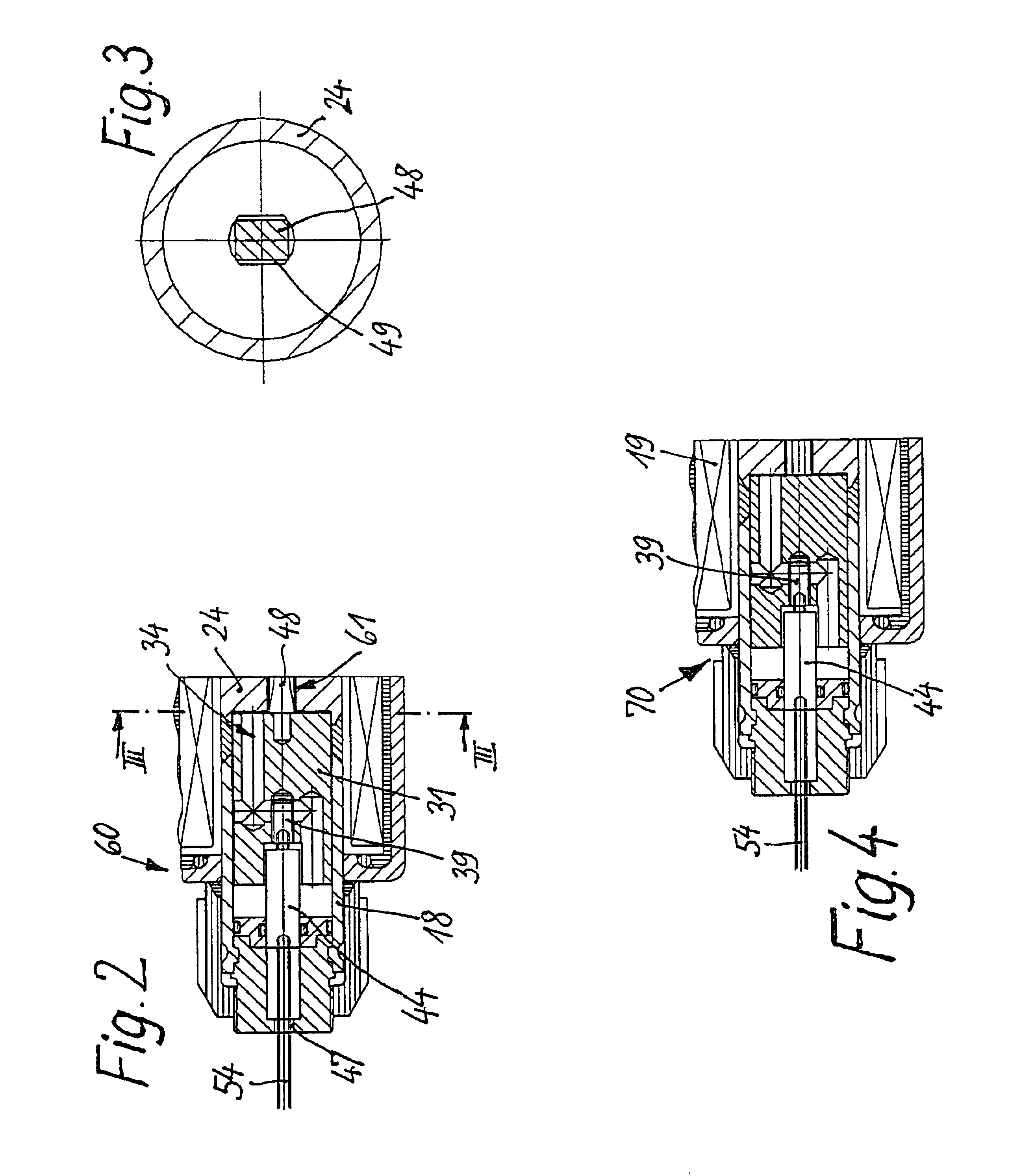
The electromagnet 10 is configured as a single-acting tractive solenoid having a pressure-tight configuration. For this purpose, it comprises a pressure pipe 18, on the outside of which a coil 19 and a magnet housing 21 having a coupler ring 22 are located. The pressure pipe 18 comprises a sleeve-shaped pole piece 24, on the free end of which a ...


PUM


Abstract

An electromagnet (10) for actuating a hydraulic on-off valve (11), has a wet-type configuration and its armature (31) is displaced in a pressure pipe (18) when a volume of oil is switched through a throttling site (35) in such a way that switching speed can be influenced. The electromagnet (10) has a manual emergency actuation device (43) in the pressure pipe (18). If necessary, the actuating bolts (44) of said device can be engaged with a throttle screw (39) by an interlocking connection (45, 42) in order to displace said throttle screw that is arranged in the armature (31). The switching speed of the distributing valve (11) can be easily regulated from the outside when the electromagnets (10) are mounted, without impairing functioning of the manual emergency actuation device.

Description

BACKGROUND OF THE INVENTIONThe invention is based on an electromagnet for actuating a hydraulic valve.An electromagnet of this type for actuating a hydraulic valve was made known in DE 37 23 747 A1, which said electromagnet is designed as a single-action magnet having a pressure-tight configuration. The armature is situated in a longitudinally displaceable manner in a pressure tube filled with a pressure medium, on the outside of which said pressure tube the coil and the magnet housing are situated. In addition, a manual emergency actuation device is provided on the electromagnet, the actuating bolt of which can be actuated by hand from the outside in case of emergency or during set-up, and, when the magnet is not energized, said actuating bolt can actuate the armature and / or the valve spool by means of its section extending into the pressure tube. In order to attain a desired reduction of switching speed with distributing valves of this type and, therefore, to prevent impacts that ...

Claims


Application Information

Patent Timeline
Patent Type & Authority Patents(United States)
IPC IPC(8): F15B13/044F15B13/04F15B13/00F16K31/06F16K31/11
CPCF15B13/0402F15B13/0407F16K31/0693F16K31/0613F15B13/044H01F7/1607H01F7/121
Inventor BRAUN, JERGSANZENBACHER, HERMANN
Owner BOSCH REXROTH AG
Why Eureka
Try Eureka