Method for laying floor panels

a technology for floor panels and laying boards, applied in the direction of walls, construction, building material handling, etc., can solve the problems of unable to recognize, and only partially destroyed locking elements

Active Publication Date: 2012-06-05
FLOORING TECH
View PDF23 Cites 64 Cited by
  • Summary
  • Abstract
  • Description
  • Claims
  • Application Information

AI Technical Summary

Benefits of technology

[0022]If there is at least one slot proceeding from the bottom of the panel for release of the locking element,

Problems solved by technology

Moreover, the profiling of the tongues with very close tolerances must ensure that the compression forces do not become too high; this could lead to destruction of the locking projection or the locking edge.
If the panel which is to be laid is tilted so t

Method used


Image

  • Method for laying floor panels
  • Method for laying floor panels
  • Method for laying floor panels

Examples


Embodiment Construction

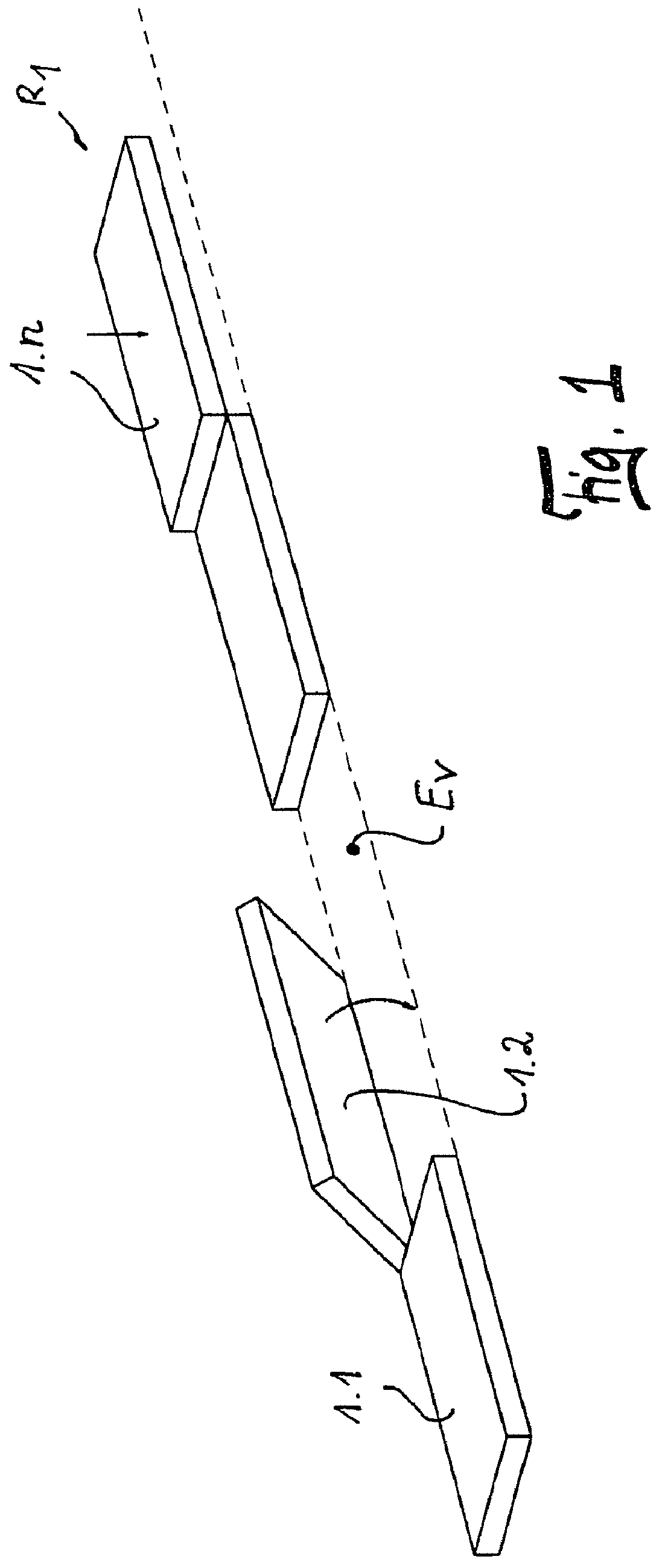
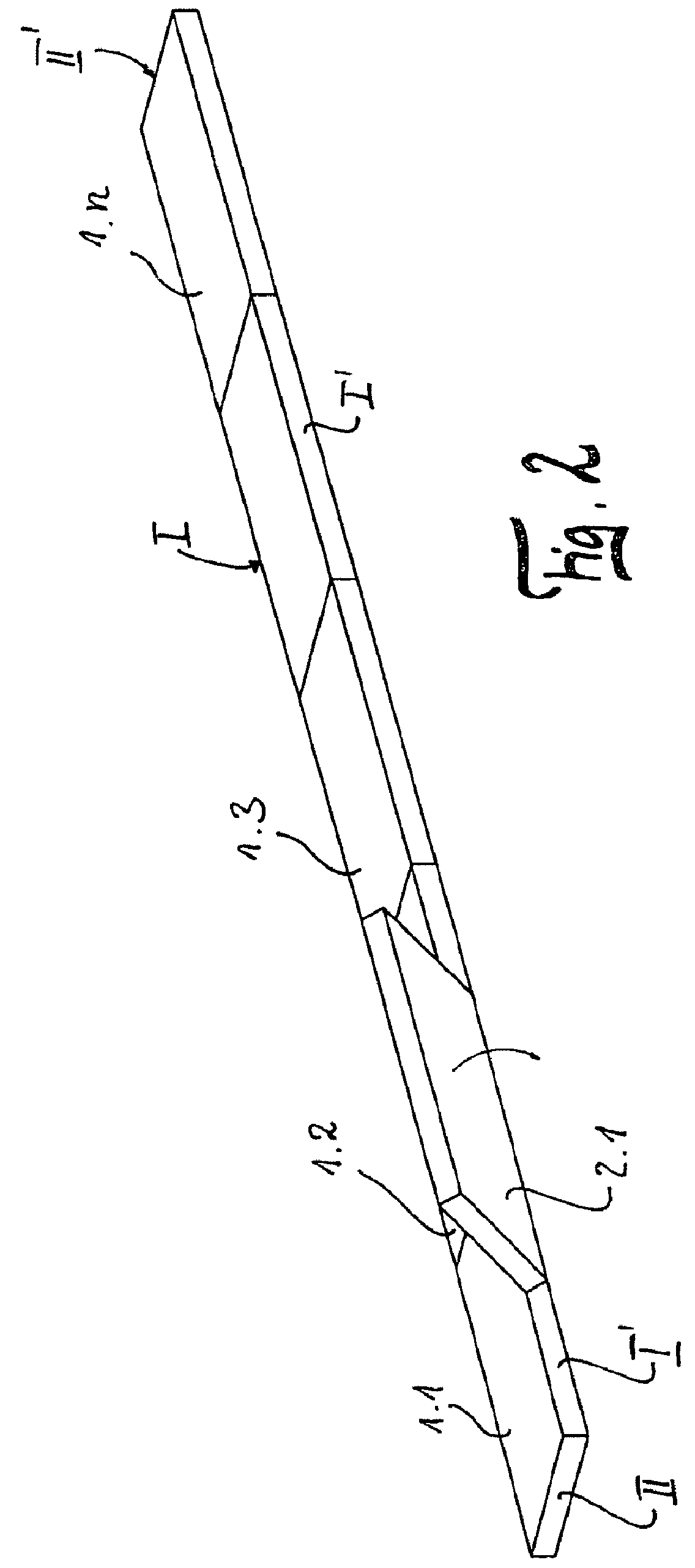
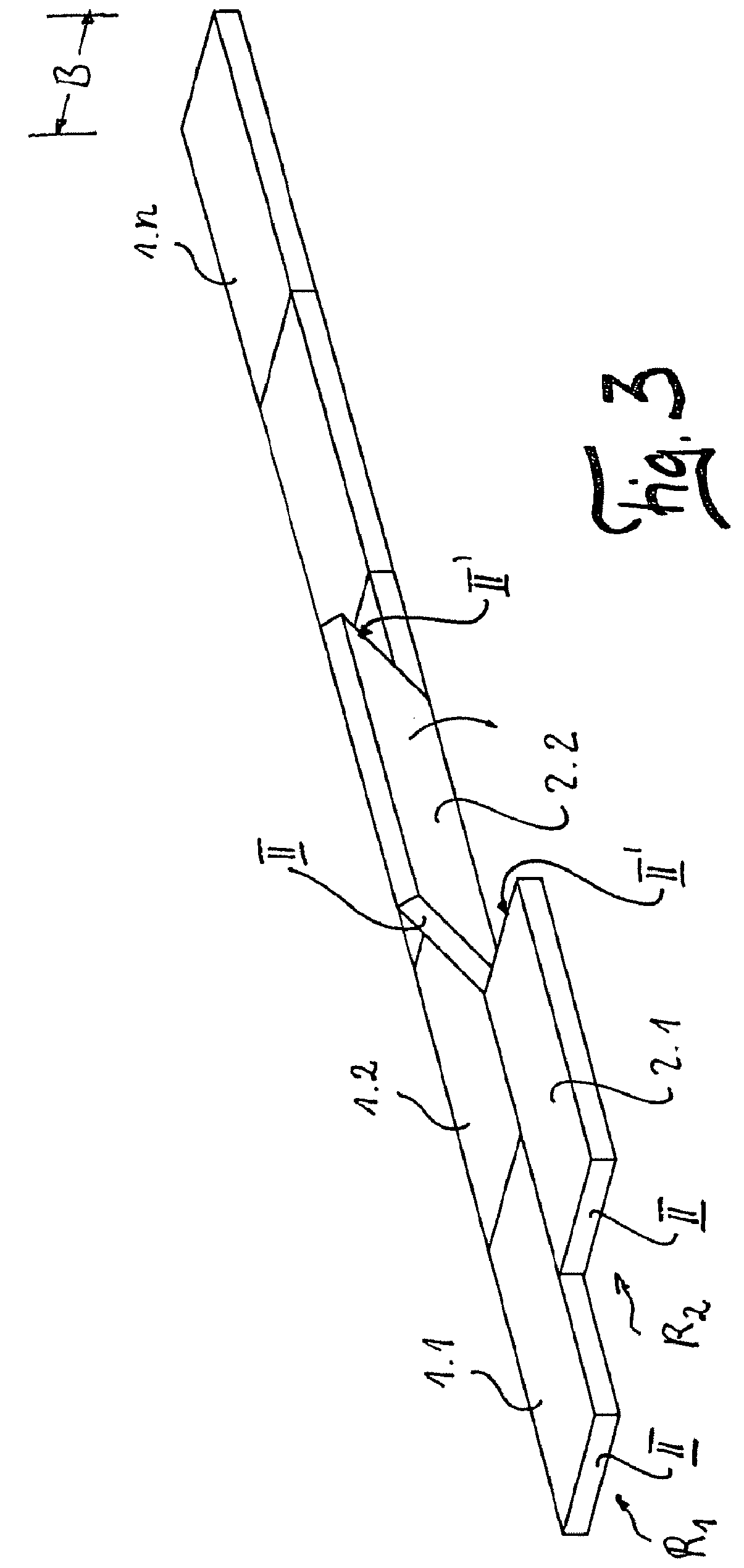
[0036]The panels 1.1, 1.2, . . . , 1.n, 2.1, 2.2, . . . are made identically. They consist of a core 17 of wood material such as HDF or MDF or a wood material-plastic mixture. On their opposing transverse edges II, II′ the panels 1.1, 1.2, . . . , 1.n, 2.1, 2.2, . . . are profiled, the transverse edge II having to be worked by milling from the top 18 and the transverse edge from the bottom 19. On the transverse edge II′ the tongue element 3 which has been produced by milling the core 17 free is made by a horizontal slot 11 and an essentially vertically running slot 10 having been milled in. The transverse edges II, II′ have a width B. Exposure of the tongue element 3 from the core 17 takes place solely by the slots 10, 11. The outer edge 3c of the tongue element 3 is tilted by an angle α relative to the transverse edge to the top 18 of the panel 1, 2. The vertical surfaces of the transverse edges II, II′ are worked such that contact surfaces 15, 16 form in the region of the top 18.

[...


PUM


Abstract

A method for laying floor panels in a room to form a closed floor area on a laying plane (R) without using an adhesive. The floor panels especially comprising a wood material, such as MDF or HDF, and having matching corresponding profiles on opposite longitudinal edges (I, I′) and transverse edges (II, II′). The closed floor area is obtained by interconnecting a plurality of panels on their transverse edges (II, II′) to give a row (R1) and on their longitudinal edges (I,I′) to give a plurality of rows (Rn) and then locking them in relation to each other.

Description

BACKGROUND OF THE INVENTION[0001]1. Field of the Invention[0002]The invention relates to a method for laying of floor panels without adhesive, especially consisting of a wood material such as MDF or HDF, which on their opposite transverse edges and longitudinal edges are provided each with profiling which corresponds to one another, in a space for forming a closed floor surface on a laying plane in which several panels with their transverse edges are joined and locked to one another into a row Ri and with their longitudinal edges into several rows Rn, in which:[0003]a) to form the first row R1:[0004]a1) a first panel is put down in the laying plane and a second panel with its transverse edge is placed against the transverse edge of the first panel and by pivoting the second panel down or lowering it vertically into the laying plane the two panels are joined and locked to one another, and[0005]a2) as many panels are joined and locked to one another in this way until the first row R1 ...

Claims


Application Information

Patent Timeline
IPC IPC(8): E04B2/00
CPCE04F15/02E04F2201/0153E04F2201/0115
Inventor BRAUN, ROGER
Owner FLOORING TECH
Why Eureka
Try Eureka