Method and apparatus for motion compensation during active intervention operations

a technology of active intervention and motion compensation, applied in the direction of survey, sealing/packing, borehole/well accessories, etc., can solve the problems of difficult setting of conventional production platforms, significant oil and gas exploration and production operations, and shifting to more challenging environments

Active Publication Date: 2012-06-05
COLES ROBERT A
View PDF22 Cites 12 Cited by
  • Summary
  • Abstract
  • Description
  • Claims
  • Application Information

AI Technical Summary

Problems solved by technology

As the world's supply of readily accessible oil and gas reserves becomes depleted, significant oil and gas exploration and production operations have shifted to more challenging environments, including deep-water locations.
Wells drilled on such locations are often situated in thousands of feet of water, which makes setting of conventional production platforms—that is, support structures permanently anchored to the sea floor—extremely difficult.
In certain water depths, installation of conventional production platforms is not possible.
In such cases, the boat, semi-submersible drilling rig or other floating vessel can move (pitch and / or roll) with the wave action of the sea, thereby creating slack in the wireline or continuous tubing string and making it difficult to perform such intervention operations on a (stationary) well or pipeline.

Method used


Image

  • Method and apparatus for motion compensation during active intervention operations
  • Method and apparatus for motion compensation during active intervention operations
  • Method and apparatus for motion compensation during active intervention operations

Examples


Embodiment Construction

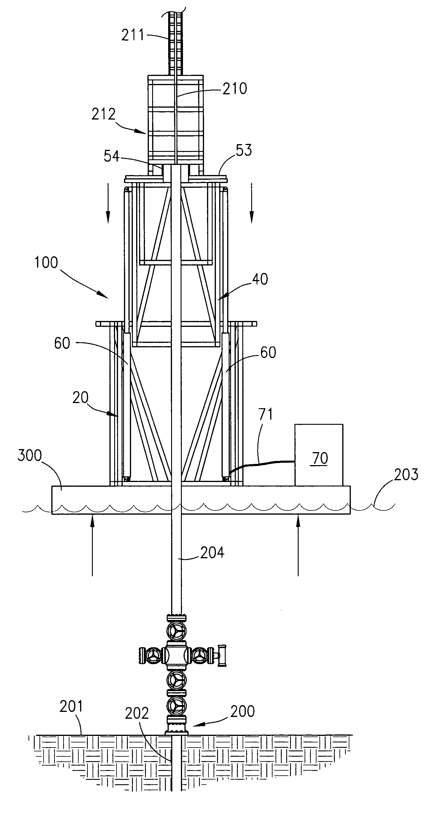
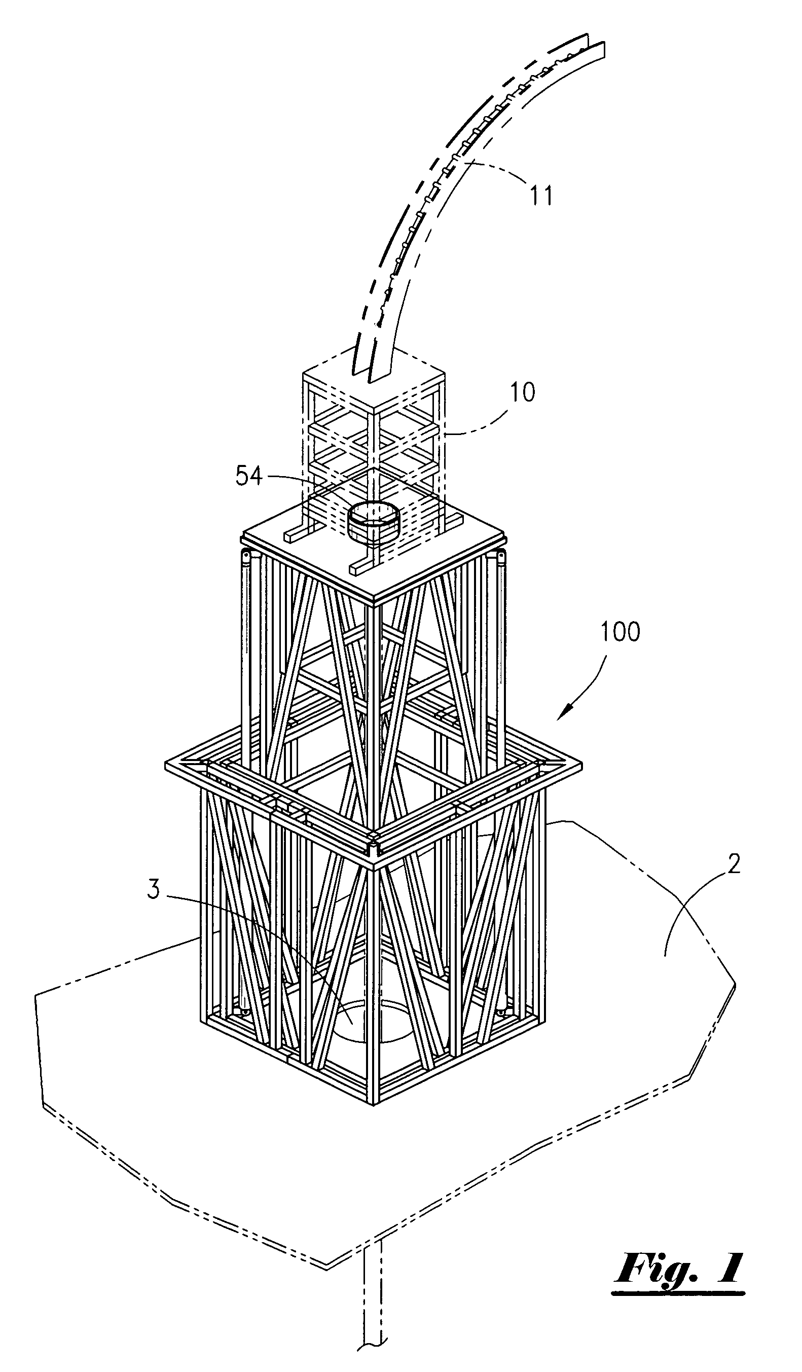
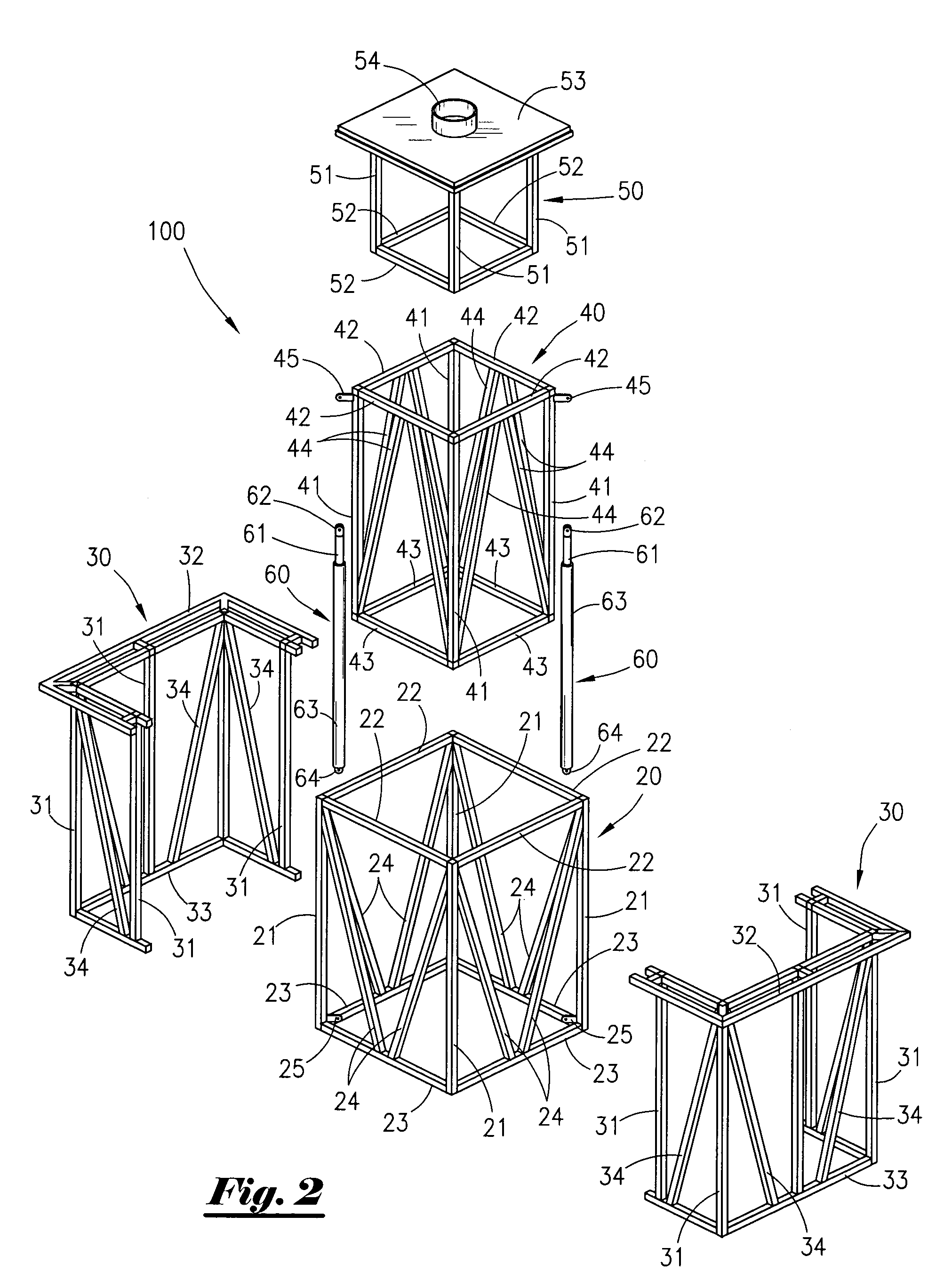
[0026]FIG. 1 depicts an overhead perspective view of the active motion compensation apparatus 100 of the present invention. Said active motion compensation apparatus 100 can be beneficially mounted on any number of surfaces. In the preferred embodiment, active motion compensation apparatus 100 is disposed on substantially flat deck 2 of a boat, semi-submersible rig or other floating vessel.

[0027]Many different intervention technologies can be used in connection with active motion compensation apparatus 100 of the present invention. FIG. 1 depicts said apparatus 100 employed with a conventional coiled tubing unit of a type well known to those having skill in the art. Said conventional coiled tubing unit includes a length of flexible continuous tubing disposed on a reel or spool (not depicted in FIG. 1). The distal end of said flexible continuous tubing is unwound from said spool, threaded through curved goose neck assembly 11 and received within injector head assembly 10 (which is it...


PUM


Abstract

This patent application applies to an Active Motion Compensation system for use during intervention or other work on subsea wells, pipelines or other structures. It could be used on existing floating production platforms such as Tension Leg Platforms (TLP) and Spar structures where intervention work including Coiled Tubing, Slickline, Electric Line, Wireline, as well as snubbing or Hydraulic Workover activities are being utilized. It could also be deployed over the side of or through the moon pool of a vessel without the need of any other compensation device.

Description

CROSS REFERENCES TO RELATED APPLICATION[0001]Priority of U.S. Provisional Patent Application Ser. No. 61 / 270,764 filed Jul. 13, 2009, incorporated herein by reference, is hereby claimed.STATEMENTS AS TO THE RIGHTS TO THE INVENTION MADE UNDER FEDERALLY SPONSORED RESEARCH AND DEVELOPMENT[0002]NONEBACKGROUND OF THE INVENTION[0003]1. Field of the Invention[0004]The present invention pertains to a method and apparatus for supporting equipment used during intervention operations conducted from marine vessels and / or offshore installations. More particularly still, the present invention pertains to a method and apparatus for compensating for motion encountered during intervention operations conducted from marine vessels and / or offshore installations including, without limitation, operations utilizing coiled tubing, slickline, electric line, wireline, snubbing and / or hydraulic workover units.[0005]2. Brief Description of the Prior Art[0006]As the world's supply of readily accessible oil and ...

Claims


Application Information

Patent Timeline
Patent Type & Authority Patents(United States)
IPC IPC(8): E21B19/09
CPCE21B19/006E21B19/22
Inventor COLES, ROBERT A.
Owner COLES ROBERT A
Why Eureka
Try Eureka