Coiled tubing clamping device and injection head using same

A clamping device and oil pipe technology, which is applied in the direction of drill pipe, casing, earthwork drilling, etc., can solve the problems of unfavorable automatic adjustment, large impact of oil pipe, short service life, etc., and achieve convenient replacement of oil pipe clamping device without lubrication , to avoid the effect of injury or wear

Active Publication Date: 2013-04-17
YANTAI JEREH OILFIELD SERVICES GROUP +1
View PDF0 Cites 112 Cited by
  • Summary
  • Abstract
  • Description
  • Claims
  • Application Information

AI Technical Summary

Problems solved by technology

The clamping block with rolling elements currently used on the injection head has the following defects: First, the rolling bearings used on the clamping device have a short service life, difficult maintenance, and inconvenient lubrication. The main defect of the holding block; the second is that due to the various sizes of the wellhead in the oil field, the size of the coiled tubing used is also different, and normal wear and tear, the injection head needs to frequently replace the holding block when it is working, but the current holding block is in the middle of the holding block. The seat is fixed in multiple places, and the replacement is complicated
Moreover, the mode of multiple fixings is used to make the movable gap of the clamping block on the clamping block seat less, which is unfavorable for the automatic adjustment when the clamping block clamps the oil pipe, resulting in a large impact of the clamping block on the oil pipe and wear on the oil pipe. serious

Method used


Image

  • Coiled tubing clamping device and injection head using same
  • Coiled tubing clamping device and injection head using same
  • Coiled tubing clamping device and injection head using same

Examples


Embodiment Construction

[0026] The specific embodiment of the present invention is described in detail below in conjunction with accompanying drawing:

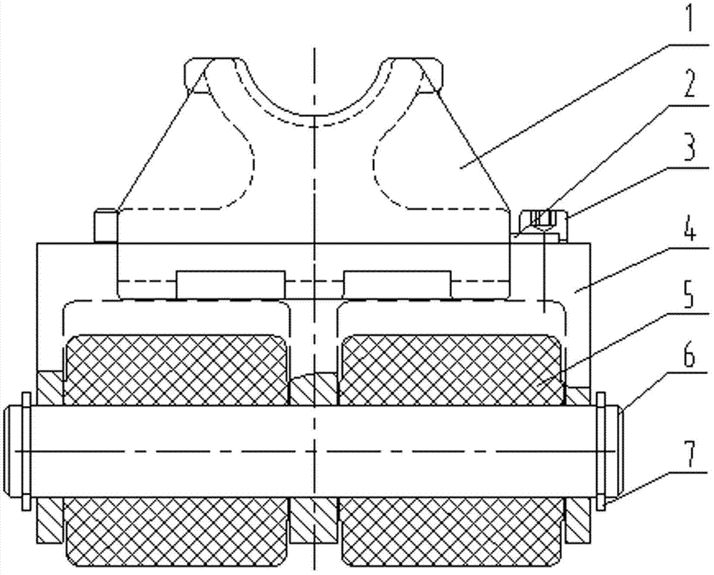
[0027] Such as Figure 1-Figure 6 Shown: a coiled tubing clamping device, including a saddle-shaped clamping block 1 and a clamping block seat 4, the saddle-shaped clamping block 1 is fixed on the clamping block seat 4 with gaps, that is, saddle-shaped clamping The block 1 can have a certain left and right movable clearance on the clamping block seat 4 along the vertical direction of the clamped oil pipe.

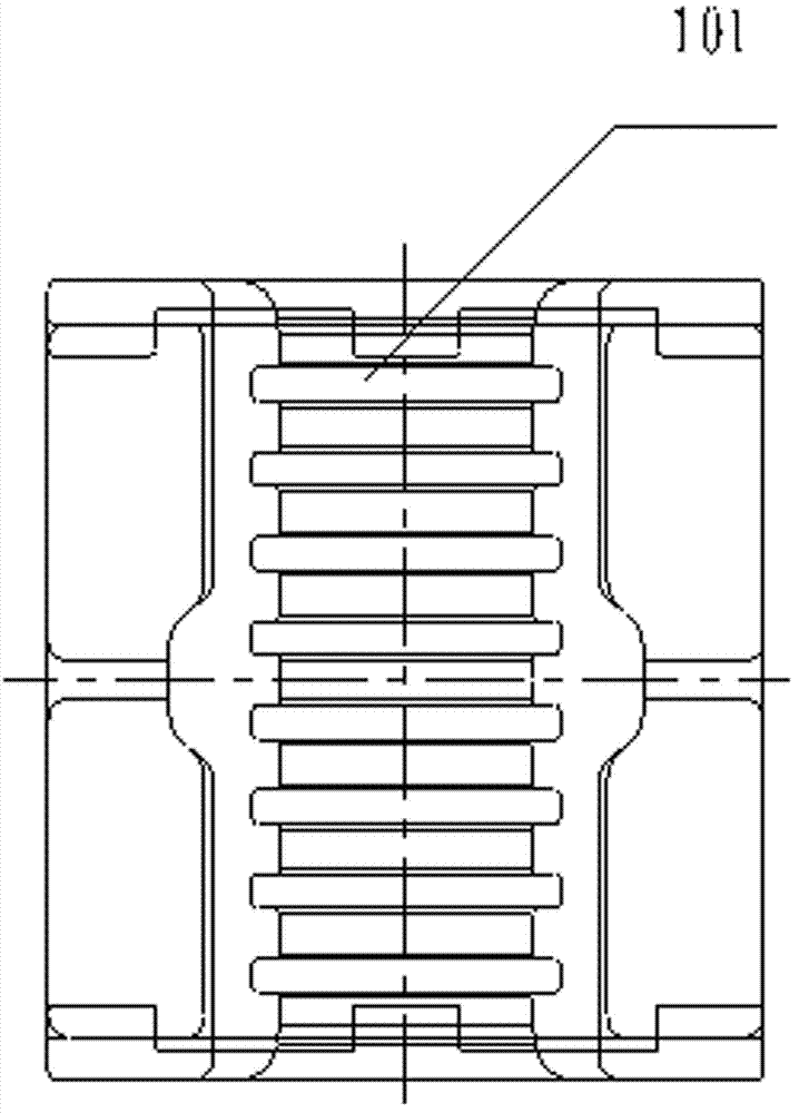
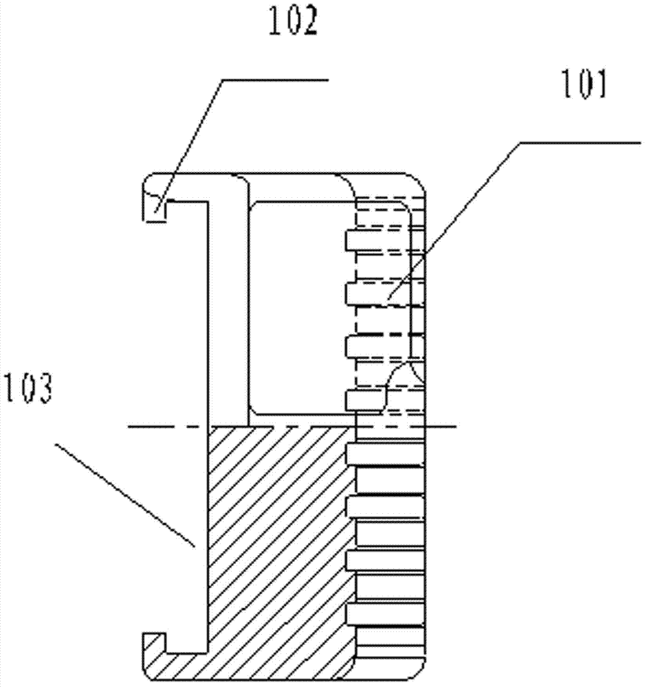
[0028] The clamping block seat 4 includes a pin shaft 6 and a ceramic rolling sleeve 5 sleeved on the pin shaft 6, and the clamping block seat 4 is provided along the direction of the pin shaft 6 with two holes for connecting with the injection head chain. The through hole 402 is provided with three partitions 406 on the upper part of the clamping block seat 4 , and a pin hole 401 for installing the pin 6 is provided on the partition 406 .

[00...


PUM


Abstract

A gripping device for a coiled tubing and an injector using the same are disclosed. The gripping device includes a saddle gripper block (1), a gripper block base (4) and a gasket (2). A recess (103) is provided on the bottom of the saddle gripper block (1), and at least two pairs of hook blocks (102) are provided on the side walls of the recess; the gripper block base (4) includes a pin shaft (6) and a rolling sleeve which is sleeved on the pin shaft (6); a limiting stand (405) and a bolt hole (404) are provided on the bottom of the gripper block base; the two sides of the gripper block base (4) are provided with bosses (403) corresponding to the hook blocks (102) of the gripper block; the gripper block base (4) is provided with two through-holes (402) along the direction of the pin shaft (6); The injector includes the gripping device for the coiled tubing and drive chains, and the gripping device for the coiled tubing is mounted on the drive chains by the two through-holes (402) in the gripper block base. The gripper block of the gripping device can be conveniently replaced, thus reducing abrasion of tubing during work. The injector has the advantages of easy maintenance and longer lifetime.

Description

technical field [0001] The invention relates to the field of oil drilling equipment, in particular to a coiled tubing clamping device, and also relates to an injection head using the coiled tubing clamping device of the invention. Background technique [0002] The injection head is the core component of the coiled tubing equipment, and the clamping device provides the clamping force for the injection head to transport the coiled tubing. The clamping block with rolling elements currently used on the injection head has the following defects: First, the rolling bearings used on the clamping device have a short service life, difficult maintenance, and inconvenient lubrication. The main defect of the holding block; the second is that due to the various sizes of the wellhead in the oil field, the size of the coiled tubing used is also different, and normal wear and tear, the injection head needs to frequently replace the holding block when it is working, but the current holding bl...

Claims


Application Information

Patent Timeline
Patent Type & Authority Patents(China)
IPC IPC(8): E21B19/22
CPCE21B19/22
Inventor 刘东于清峰方基垒
Owner YANTAI JEREH OILFIELD SERVICES GROUP
Why Eureka
Try Eureka