Well system

a technology of a well system and a well head is applied in the field of well systems, which can solve the problems of preventing the use of such expensive rigs, requiring as much as $250,000 a day for lease, and requiring approximately $40 million to build off-shore drilling rigs, so as to reduce the cost of expensive and somewhat fragile downhole electronic components, reduce the cost of vibration, and reduce the cost of less expensiv

Inactive Publication Date: 2005-06-02
HALLIBURTON ENERGY SERVICES INC
View PDF99 Cites 110 Cited by
  • Summary
  • Abstract
  • Description
  • Claims
  • Application Information

AI Technical Summary

Benefits of technology

[0040] Another advantage of the present invention is the use of a bottom hole assembly which is anchored to the borehole thus minimizing much of the vibration encountered by conventional bottom hole assemblies. Vibration, harmonics and shock are very damaging to conventional bottom hole assemblies and particularly the electronic components in such assemblies.
[0041] Another advantage of the present invention is the use of electrical conductors extending through the composite coiled tubing. By conducting electrical power between the surface and the bottom hole assembly, alternators and batteries are no longer required in the bottom hole assembly to operate the electronic components.
[0042] A further advantage of the present invention is the use of data transmission conduits, such as copper wire, fiber optic cable or coaxial cable, passing through the wall of the composite coiled tubing. Such data transmission conductors allow the transmission of raw data received by the sensors in the bottom hole assembly for real time transmission directly to the surface without exposing the wire which could then be damaged. The data then can be processed at the surface rather than downhole s

Problems solved by technology

Many existing wells include hydrocarbon pay zones which were bypassed during drilling and completion because such bypassed zones were not economical to complete and produce.
Offshore drilling rigs cost approximately $40 million to build and may cost as much as $250,000 a day to lease.
Such costs preclude the use of such expensive rigs to drill and complete these bypassed hydrocarbon pay zones.
Presently, there is no cost effective methods of producing many bypassed zones.
The depth that can be drilled using a thruster is limited.
However, there is very little clearance between the wheels of the propulsion system and the wall of the borehole and problems arise when the wheels encounter ridges or other variances in the dimensions of the wall of the borehole.
Further, at times there is an inadequate frictional engagement between the wheels and the wall of the borehole to adequately propel the tractor.
Buckling is particularly acute in deviated wells where gravity does not assist in forcing the tubing downhole.
As the tubing buckles, the torque and drag created by the contact with the borehole becomes more difficult to overcome and often makes it impractical or impossible to use coiled tubing to reach distant bypassed hydrocarbon zones.
Further, steel coiled tubing often fatigues from cyclic bending early in the drilling process and mu

Method used


Image

  • Well system
  • Well system
  • Well system

Examples


Embodiment Construction

[0068] The present invention is susceptible to embodiments of different forms. There are shown in the drawings, and herein will be described in detail, specific embodiments of the present invention with the understanding that the present disclosure is to be considered an exemplification of the principles of the invention, and is not intended to limit the invention to that illustrated and described herein.

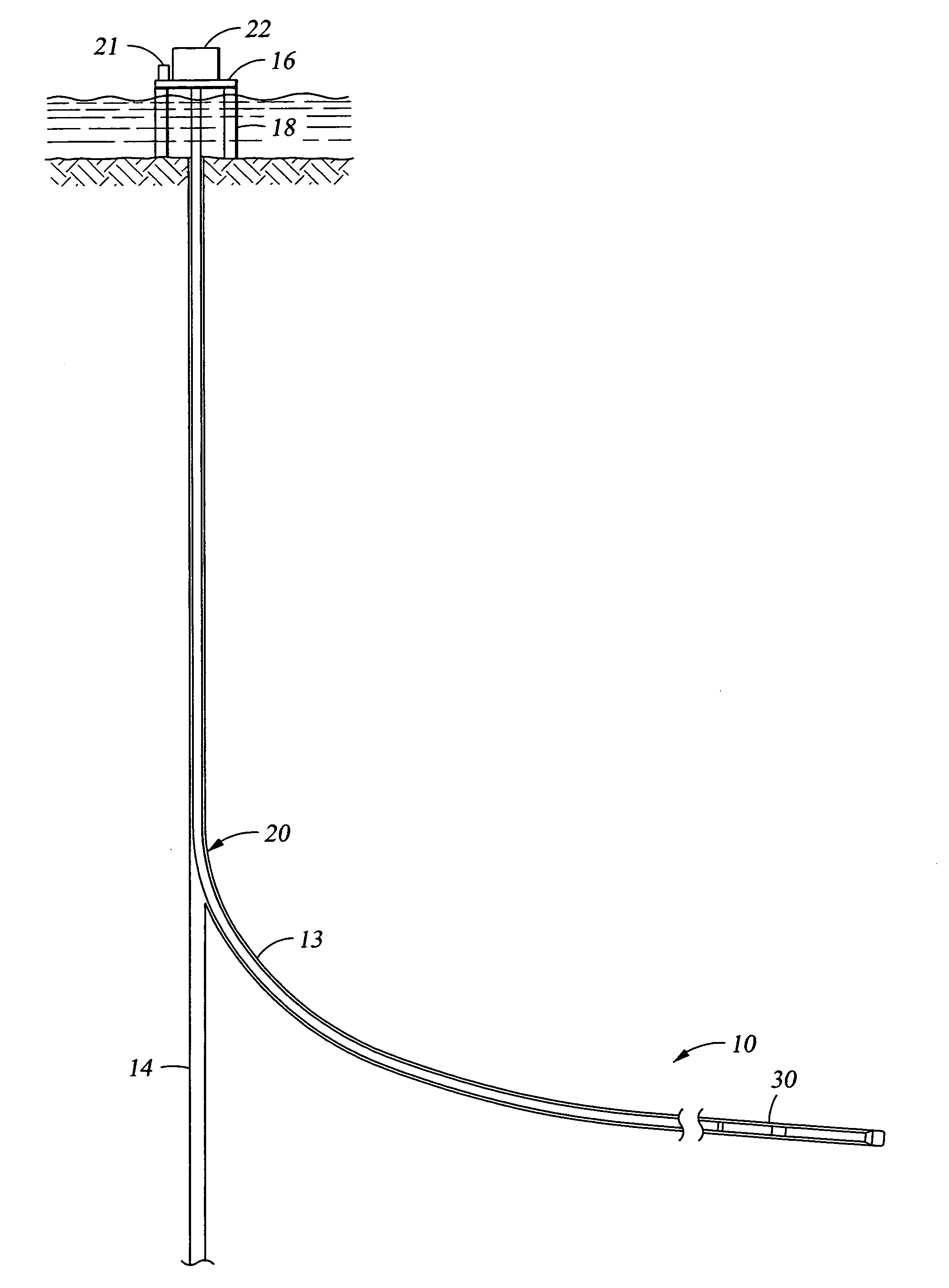
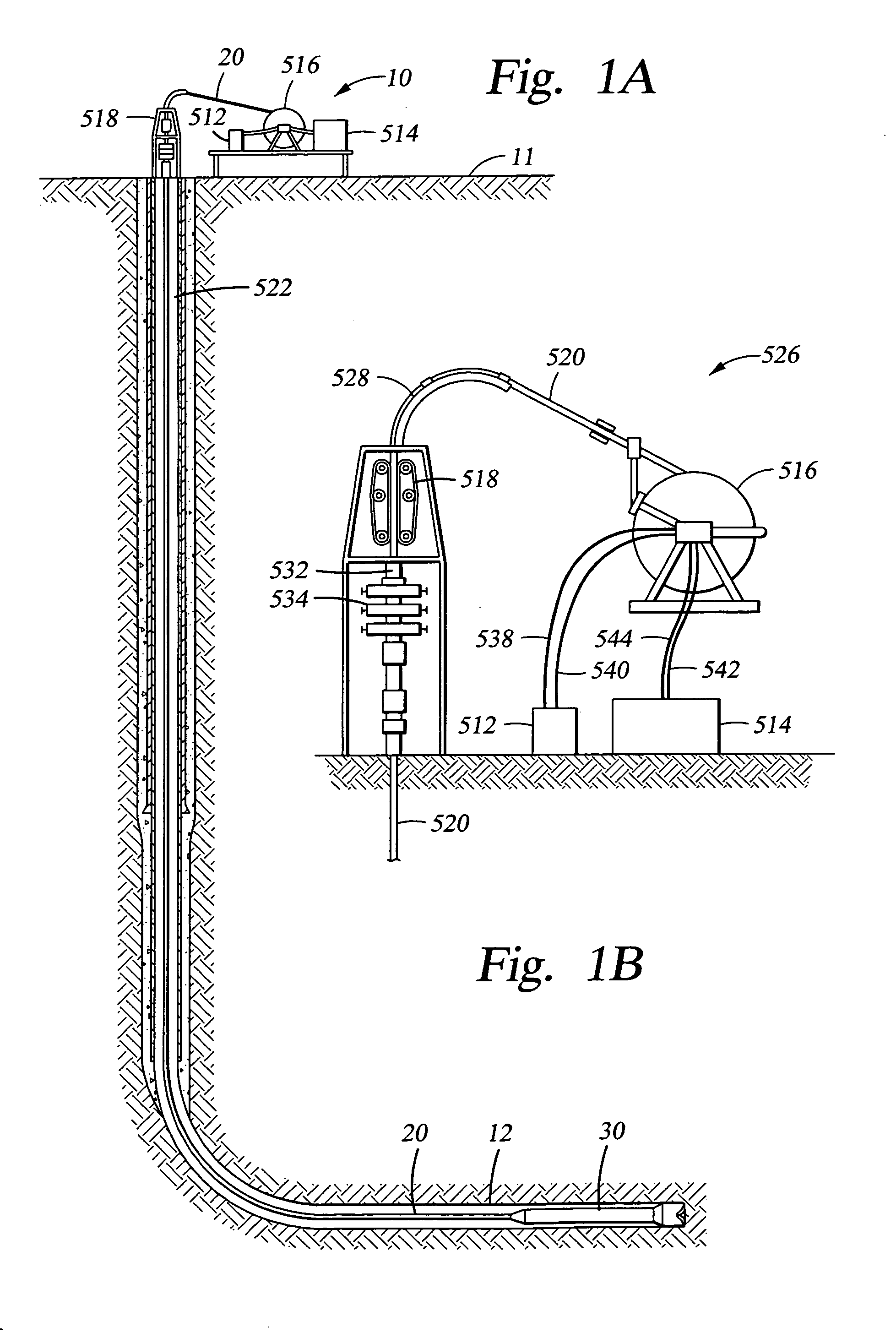
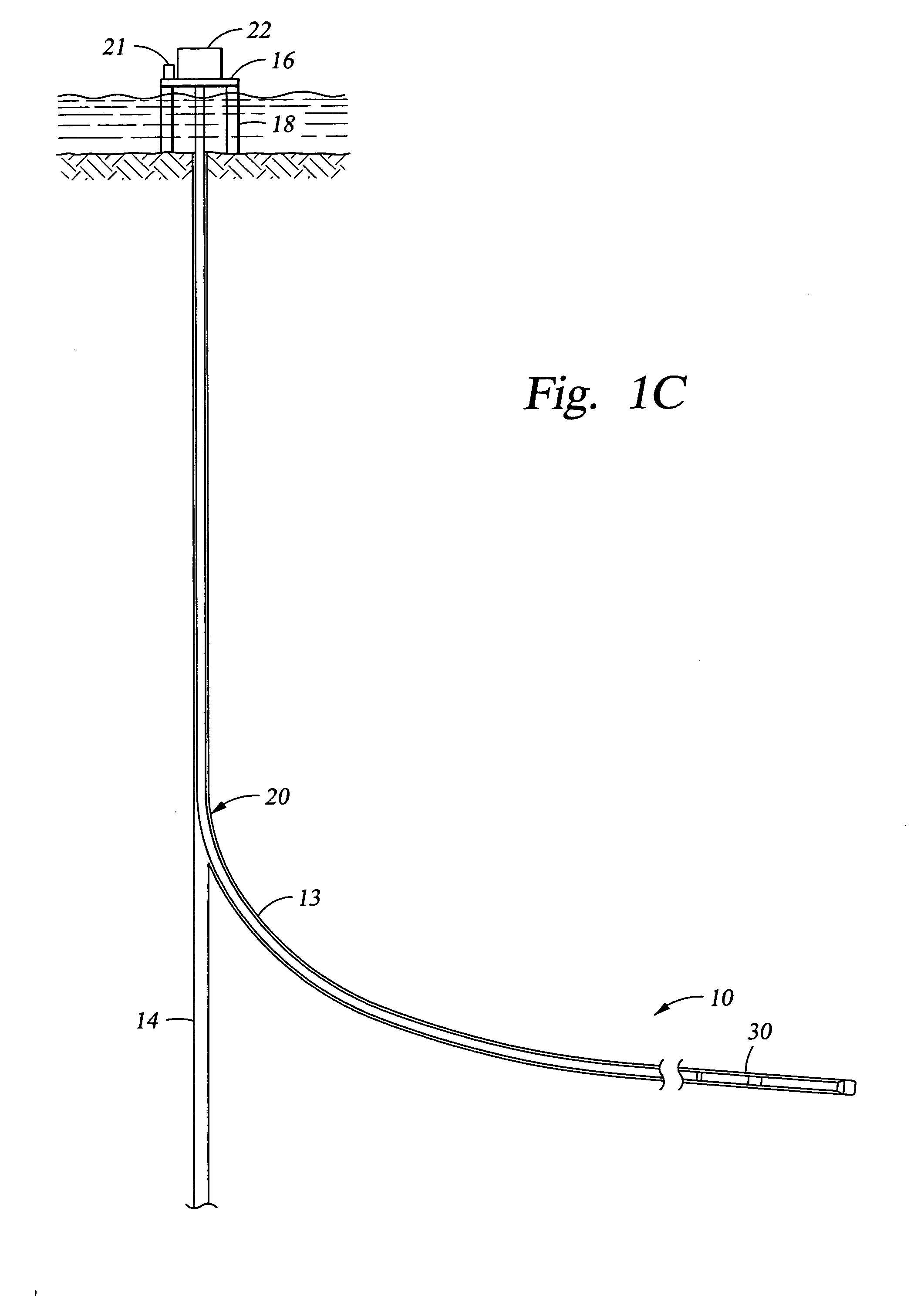
[0069] The system of the present invention includes a composite coiled tubing having a bottom hole assembly attached. Various embodiments of the present invention provide a number of different constructions of the bottom hole assembly, each of which is used for a downhole operation in one of many different types of wells including a new well, an extended reach well, extending an existing well, a sidetracked well, a deviated borehole, and other types of boreholes. It should be appreciated that the bottom hole assembly may be only a downhole tool for performing an operation downhole ...


PUM


Abstract

The drilling system includes a work string supporting a bottom hole assembly. The work string including lengths of pipe having a non-metallic portion. The work string preferably includes a composite coiled tubing having a fluid impermeable liner, multiple load carrying layers, and a wear layer. Multiple electrical conductors and data transmission conductors may be embedded in the load carrying layers for carrying current or transmitting data between the bottom hole assembly and the surface. The bottom hole assembly includes a bit, a gamma ray and inclinometer instrument package, a steerable assembly, an electronics section, a transmission, and a power section for rotating the bit. It may or may not include a propulsion system. The drilling system may be a gravity based drilling system that does include a propulsion system. Various motive means may be provided, such as gravity, to apply weight on the bit.

Description

CROSS-REFERENCE TO RELATED APPLICATIONS [0001] This application is a divisional of U.S. patent application Ser. No. 10 / 265,786 filed Oct. 7, 2002 and entitled “Well System, which the benefit of 35 U.S.C. 119(e) of U.S. provisional application Ser. No. 60 / 353,654, filed Feb. 1, 2002 and entitled Well System and is a continuation-in-part of U.S. patent application Ser. No. 09 / 911,963 filed Jul. 23, 2001 and entitled “Well System” which is a continuation application of U.S. patent application Ser. No. 09 / 081,961, filed May 20, 1998 and entitled “Well System,” now U.S. Pat. No. 6,296,066, which claims the benefit of 35 U.S.C. 119(e) of U.S. Provisional Application Ser. No. 60 / 063,326, filed Oct. 27, 1997 and entitled “Drilling System”, all hereby incorporated herein by reference. The present application is also related to the following applications: U.S. application Ser. No. 09 / 845,473, filed Apr. 30, 2001 and entitled Borehole Retention Assembly, U.S. application Ser. No. 09 / 739,072 fi...

Claims


Application Information

Patent Timeline
IPC IPC(8): E21BE21B4/00E21B4/18E21B7/00E21B7/06E21B7/08E21B17/00E21B17/02E21B17/03E21B17/20E21B19/07E21B19/086E21B19/16E21B19/22E21B23/00E21B29/00E21B29/06E21B47/01E21B49/08G01V3/30G01V11/00
CPCE21B2023/008G01V3/30G01V11/002E21B4/18E21B7/068E21B17/028E21B47/01E21B17/206E21B19/07E21B19/086E21B19/161E21B29/06E21B17/03E21B23/001
Inventor TERRY, JAMES B.WILSON, THOMAS PLATTEPPINK, JAY M.ODELL, ALBERT C.TRAINOR, WILLIAM F.ESTEP, JAMES W.SONG, HAOSHI
Owner HALLIBURTON ENERGY SERVICES INC
Why Eureka
Try Eureka