Agricultural field sprayer and process for its operation

a technology for spraying machines and agricultural fields, applied in watering devices, roads, maintenance, etc., to achieve the effects of increasing the rotational speed of the motor, increasing the pump output, and increasing the flow ra

Active Publication Date: 2012-06-05
JOHN DEERE FAB HORST +1
View PDF12 Cites 53 Cited by
  • Summary
  • Abstract
  • Description
  • Claims
  • Application Information

AI Technical Summary

Benefits of technology

[0005]According to the invention an agricultural field sprayer of the kind cited initially is equipped with an electric motor to drive the pump. The return line and the sprayer line each include at least one electrically operated control valve. An electronic control system connected to the motor and the control valve structure controls the motor and valve structure as a function of the vehicle speed of the field sprayer. It is also possible to control the motor as a function of the desired application amount, partial width spraying area, and / or desired mixture application rate. Since an electric motor is used to drive the pump in combination with the aforementioned control valve structure in the return and sprayer lines, the required flow rate can be optimized in terms of the various adjustable operating conditions including vehicle speed. Precise fluid control depending on the various function or operating mode of the vehicle, including a stopped condition of the vehicle, can be achieved without conventional bypass valves and the disadvantages of conventional bypass valve systems. Vehicle speed sensing for purposes of providing a speed signal to a controller can be provided by a speed sensor or by rotational speed sensors on the towing vehicle or on the field sprayer. Miscellaneous vehicle data or vehicle signals such as a vehicle speed signal or an acceleration signal can then be recalled in the usual and known manner for purposes of control. Since an operation of the field sprayer can be performed independently of the power take off shaft of the tractor further advantages can be attained. Since the limitations of a power take off shaft are removed, small turning radii can be attained. Furthermore, the tractor and the field sprayer no longer need to be carefully matched to each other, and costly maintenance procedures associated with an articulated drive shaft driven by a power take off shaft are eliminated. Coupling the field sprayer to the tractor can be performed much more easily and comfortably since simpler attachment couplings are used. By driving the pump with an electric motor independently of any mechanical coupling or towing vehicle engine speed, excessive pump speeds and the disadvantages of a power take off drive are avoided. The sprayer tank filling processes can be performed at a low idle speed of the towing vehicle since the pump power requirements need not depend on the power take off shaft output. Higher efficiencies can be expected since continuously variable drive rotational speeds are possible.
[0017]The process provides independent control of the recirculation rate even, for example, when the control valve in the sprayer line is fully opened and the control valve provided in the return line is closed or it is opened as a function of the further increasing or decreasing motor rotational speed. The result is that when the flow rate in the sprayer line is further increased or decreased, the recirculation rate of the sprayer fluid contained in the tank is controlled independently of the change and may, for example, be held constant or even reduced or increased.

Problems solved by technology

Precise fluid control depending on the various function or operating mode of the vehicle, including a stopped condition of the vehicle, can be achieved without conventional bypass valves and the disadvantages of conventional bypass valve systems.

Method used


Image

  • Agricultural field sprayer and process for its operation
  • Agricultural field sprayer and process for its operation
  • Agricultural field sprayer and process for its operation

Examples


Embodiment Construction

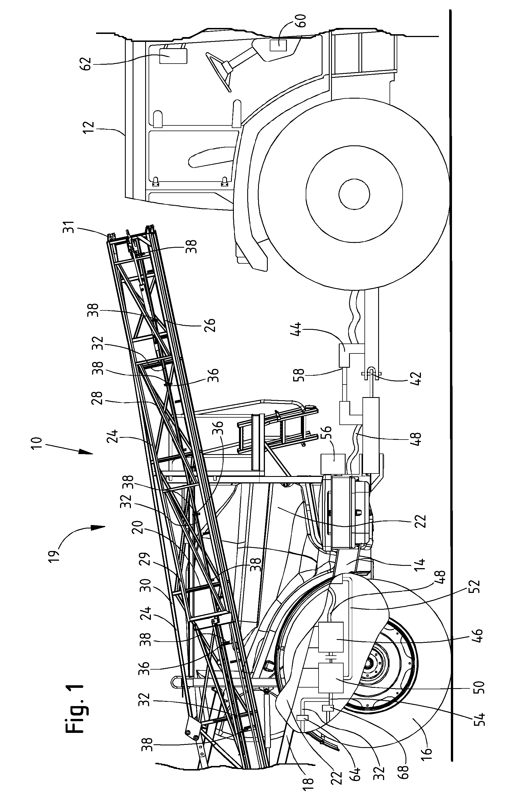
[0025]FIG. 1 shows an agricultural field sprayer 10 which, by way of example only, is depicted as a towed field sprayer connected to a tractor 12. A self-propelled field sprayer or an attached field sprayer could also be used. The sprayer 10 includes a frame 14 with wheels 16. A parallel linkage 18 with a trailing sprayer arrangement 19 is attached to the frame 14. The sprayer arrangement 19 includes sprayer gear or a spray boom assembly 20. A tank 22 mounted on the frame 14.

[0026]The sprayer gear 20 includes upper and lower carriers or tubes 24, 26, connected by a plurality of struts 28 that form a framework. The sprayer gear 20 is composed of several partial areas 29, 29′, 30, 30′ that are connected to each other by hinges 31 and that extend on either side of the sprayer 10. The sprayer gear 20 can be folded into a transport position by means of the hinges 31 as shown in FIG. 1 or unfolded to a conventional operating position.

[0027]The sprayer gear 20 is equipped with a sprayer li...


PUM


Abstract

An agricultural field sprayer (10) includes an electrically driven pump (50) locatable directly under sprayer fluid tank for conveying the fluid from the tank to a supply line. A return line (54) connects the pump (50) to the tank (22), and a sprayer line (32) connecting the pump (50) to an application assembly (20). The return line (54) and the sprayer line (32) include electrically operated control valves (68, 64), and an electronic control system (56) operates the motor (46) and the control valves (64, 68) as a function of different variables including field sprayer speed and sprayer fluid characteristics. The valve and motor controls and an additional valve-controlled return line facilitate numerous operational modes including tank fill, rinse, recirculation, spray, partial width spray, and stop modes.

Description

FIELD OF THE INVENTION[0001]The invention concerns an agricultural field sprayer with a tank to store sprayer fluid, sprayer gear for the application of sprayer fluid, a pump for the conveying of sprayer fluid, a supply line connecting the tank with the sprayer, a return line connecting the pump with the tank and a sprayer line connecting the pump with the sprayer gear. Furthermore the invention concerns a process for the operation of an agricultural field sprayer.BACKGROUND OF THE INVENTION[0002]Agricultural field sprayers are known in which the pumps used to convey sprayer fluid are driven hydraulically or mechanically. In the case of towed sprayers a tractor power take-off shaft or hydraulic motors driven from a hydraulic source on the tractor provide power. Pumps driven in such a way are usually operated at a constant pump rotational speed so that constant amounts of fluid are conveyed. The amounts conveyed or the flow rates are varied by means of bypass valves to adjust the flo...

Claims


Application Information

Patent Timeline
Patent Type & Authority Patents(United States)
IPC IPC(8): B05B9/06B05B1/20B05B9/00
CPCA01C23/007A01M7/0089B05B9/06
Inventor HAHN, KLAUSEBERBACH, HEIKOHIRSCHPEK, RALFPEETERS, WILLYLORENTZEN, ROBERT E.KLEMME, KENT ALVIN
Owner JOHN DEERE FAB HORST
Why Eureka
Try Eureka